Chapter 1. Installation
43
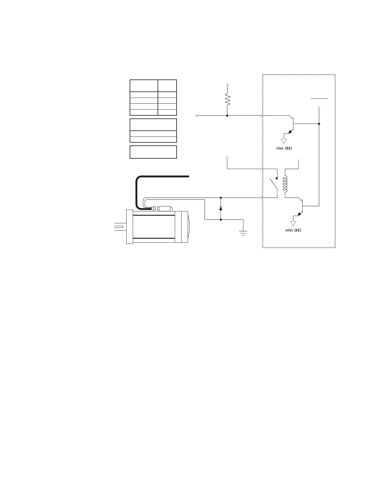
EXAMPLE 1: APEX Series motors are available from Compumotor with an optional
mechanical brake. Call Compumotor’s Customer Service Department (800-722-2282) for
more information. The next drawing shows how to connect the brake to the fault relay
terminals.
Fault Relay+
Fault Relay–
+5VDC to +24VDC
Pull-up
Resistor
Fault Out
Fault All
Resolver Cable
Flying Leads for Brake
(from Resolver Connector)
+5VDC
+24VDC
Optional
Diode
(1N4936)
Drive
Condition
Power OFF
Disabled
Faulted
Enabled
Relay
State
Open
Open
Open
Closed
Fault Relay
Max Current Rating
5A at 24VDC, or
5A at 120VAC
Relay Type:
Normally Open
Internal Schematic
APEX615n
Fault Relay with Mechanical Brake
24VDC is applied, through the fault relay terminals, to one of the flying leads on the motor's
resolver connector. The other lead is connected to ground. An optional diode is shown installed
between the two leads. The diode's polarity is correct as shown.
The drawing also shows that the fault output and the fault relay are controlled by the same
internal signal. Any fault condition that triggers the fault output will also cause the fault relay
to turn off (relay will be opened).
You can also use external resistors for motor braking, as the next example shows.
Artisan Technology Group - Quality Instrumentation ... Guaranteed | (888) 88-SOURCE | www.artisantg.com

 Loading...


