20
APEX615n Installation Guide
2. If you must connect to a GND terminal, use a separate ground wire
from your remote device. Do not put a jumper between GND and
Iso GND.
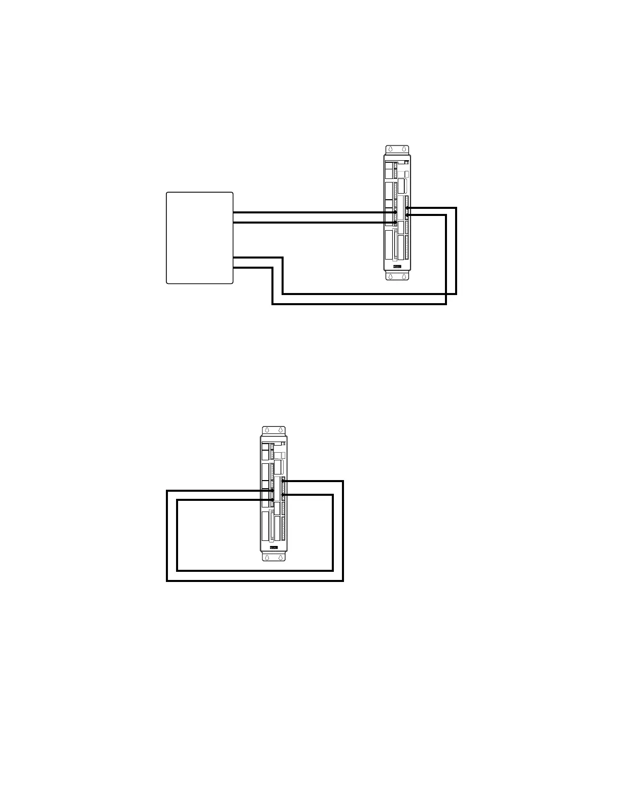
If you connect signals from an external device to terminals on both the left row of connectors
and the right row of connectors, then run two separate ground wires from the remote device to
the APEX615n. Connect one wire to Iso GND, and connect the other to GND. The next drawing
shows how to make these connections.
Encoder Output
Auxiliary
Limits
External Encoder Input
RP 240
RS 232
Programmable Inputs/Outputs
APEX615n
Compumotor
Remote
Device
Signal 1
Ground
Ground
Gnd
Signal 2
Iso Gnd
Signal 1
Signal 2
Ground Connection to both Iso GND and GND
Separate ground wires will ensure that the isolated ground remains truly isolated from the
chassis ground.
3.
If you make connections between terminals on the left row of
connectors and the right row of connectors, connect the internal
grounds together by placing a jumper between
Iso GND
and
GND.
As an example, the next drawing shows the output OUT-A controlling the RESET input on the
Drive Auxiliary connector.
Encoder Output
Auxiliary
Limits
External Encoder Input
RP 240
RS 232
Programmable Inputs/Outputs
APEX615n
Compumotor
Gnd
Reset
Iso Gnd
Out-A
Out-A
Iso Gnd
Notice that a jumper connects Iso
GND to GND. This ensures that both
signals—OUT-A and RESET—are
referenced to the same ground level.
Ground Connection Between Iso GND and GND
4 . Connect shields on interface cables at the remote device only. Do
not connect the shields at the APEX615n end.
The cable shield from a remote device, such as an external encoder or an RP240 Remote
Operator Panel, should not be connected to the APEX615n.
EXCEPTION: The shield on the motor cable should be connected to the MOTOR GROUND
terminal on the motor connector. The shield on the resolver cable should be connected to the
SHIELD terminal on the resolver connector.
Artisan Technology Group - Quality Instrumentation ... Guaranteed | (888) 88-SOURCE | www.artisantg.com

 Loading...


