Parker Hannifin S.p.A. - S.B.C. Division HPD N User’s Manual
107
Using the incremental encoder connection, you can connect an RS-422 5V differential
auxiliary encoder. On the same connector, the voltage of the encoder itself is also available.
To program the voltage see the relative table.
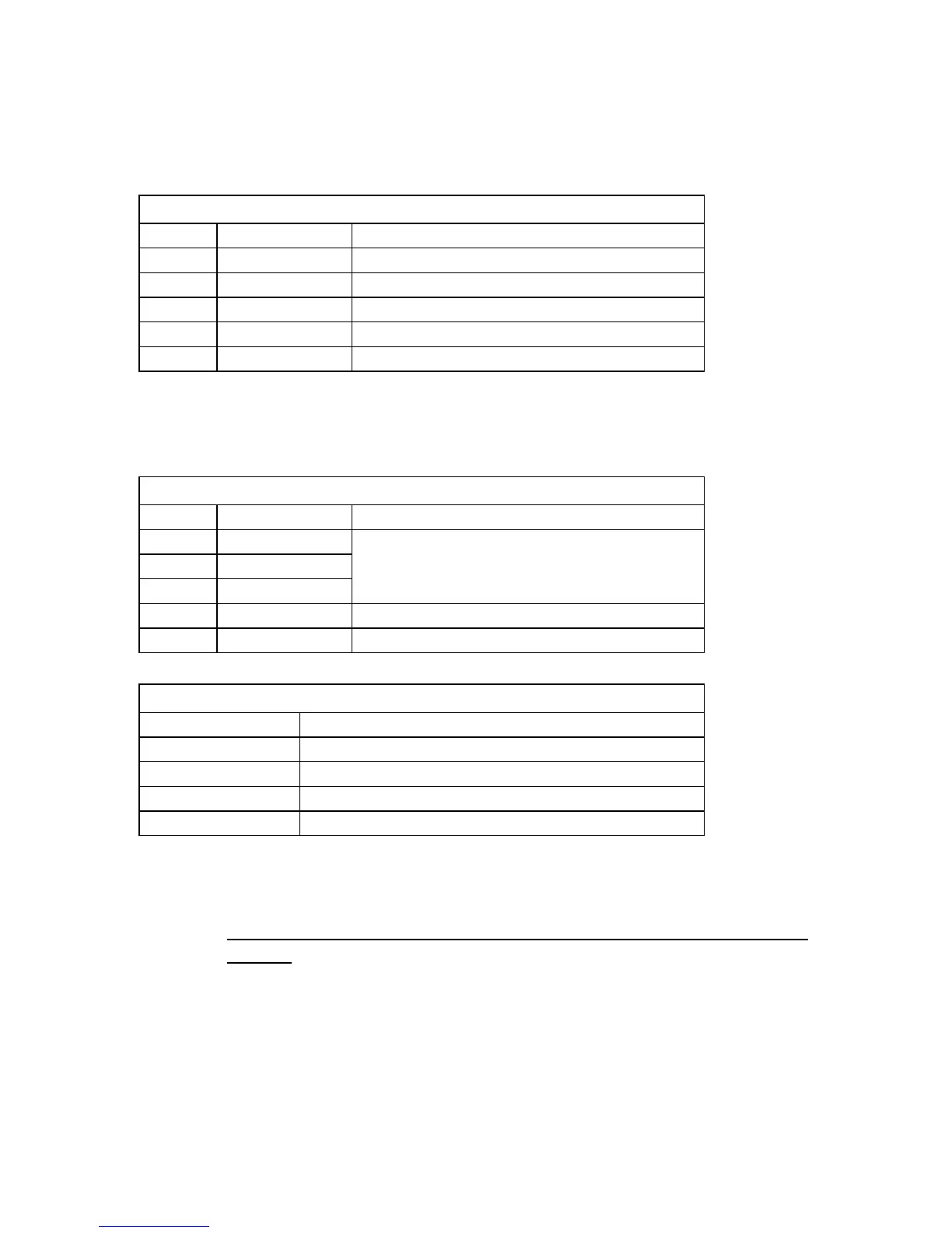
Encoder SSI CONNECTION
N. Pin Signal Description
14 Data+ Line data trasmission positive
15 Data- Line data trasmission negative
11 Clock+ Line clock positive
24 Clock- Line clock negative
21 GND 0V
Using the SSI encoder connection, you can connect an absolute auxiliary encoder based on
the SSI standard. On the same connector, the voltage of the encoder itself is also available. To
program the voltage see the relative table.
Encoder CONNECTION SUPPLY
N. Pin Signal Description
12 +V out
13 +V out Encoder voltage supply
25 +V out
22 GND 0V
9 GND 0V
Encoder supply setup
Voltage Connection
5V
8V 22 - 23
12V 9 - 10
15V 9 - 10 22 - 23
By short-circuiting the pins of the connector as shown in the table, you will have a V out able
to put out 250mA which can be used to power the auxiliary encoder.
N.B. A 220 ohm receiver-side resistor must be installeld on all differential
signals.