Parker Hannifin S.p.A. - S.B.C. Division HPD N User’s Manual
106
19. Encoder and serial link
The encoder connector and serial link is a 25-pin female connector.
The pins of the encoder connector and serial link change meaning as a function of the
connection and the drive software installed. The following tables present the typical
configurations.
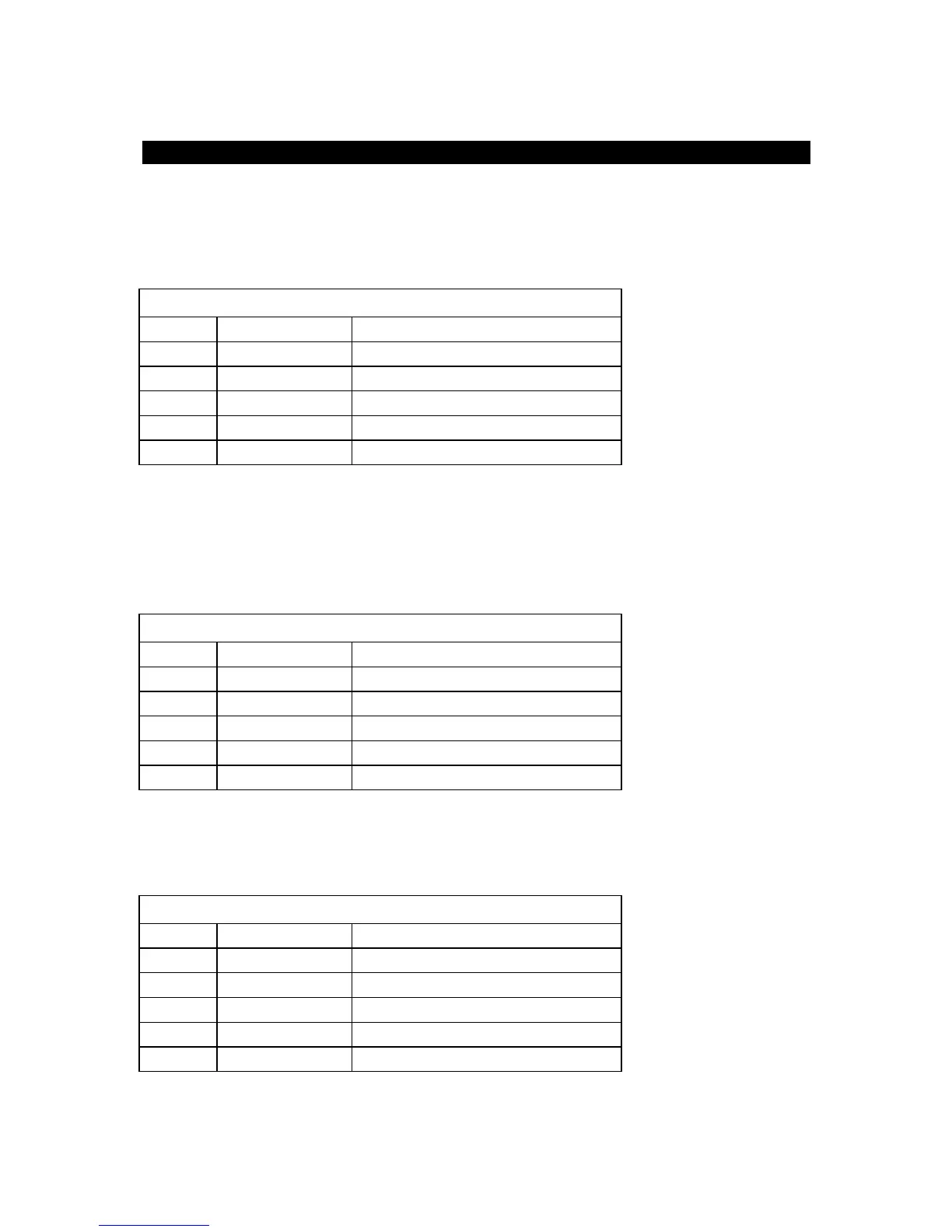
DEBUG MODE CONNECTION
N. Pin Signal Description
1 TX+ line TX RS-422 positive
2 TX- line TX RS-422 negative
3 RX+ line RX RS-422 positive
4 RX- line RX RS-422 negative
6 GND 0V
With the “DEBUG MODE” connection and using an RS-422/RS-232 converter, you can
connect the EC-4 board to a personal computer and, using the software installed on the PC,
test the user program.
Using the same communication port, you can also load software already installed in the flash
memory of the EC-4 board.
ModBus CONNECTION
N. Pin Signal Description
1 TX+ line TX RS-422 positive
2 TX- line TX RS-422 negative
3 RX+ line RX RS-422 positive
4 RX- line RX RS-422 negative
6 GND 0V
The ModBus connection makes it possible to connect a ModBus-configured operator panel to
the EC-4 board. To manage the ModBus, you need to load the drive software that will
provide access to the entire parameter area for the operator panel.
IncrementalEncoder CONNECTION
N. Pin Signal Description
14 A+ Phase A positive
15 A- Phase A negative
16 B+ Phase B positive
17 B- Phase B negative
21 GND 0V