Parker Hannifin S.p.A. - S.B.C. Division HPD N User’s Manual
76
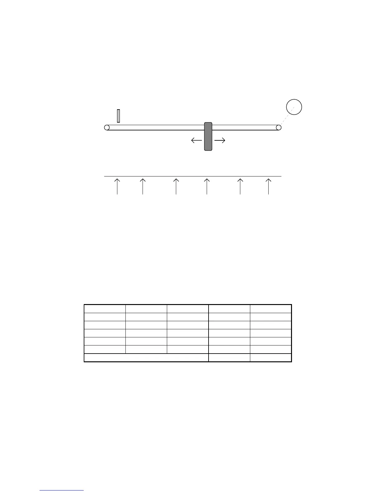
Example 12: 5 positioning
(FILE: E004.HPD)
Referring to the figure below, assume you need to move the carriage to 5 different
positions selected by means of three digital signals.
The positions are set in parameters Pr80...Pr89 in resolver steps taking the position of the
proximity sensor as the zero value. When the machine is powered up the drive remains in
standby mode awaiting the homing execution command: when a pulse command is supplied
to digital input 2 of the HPD drive the motor shaft will turn at the speed set in parameter Pr5
until the proximity switch provides a signal at digital input 3. At this point digital inputs 4, 5
and 6 select the position to be reached, while a pulse on digital input 1 makes it possible to
perform positioning on a trapezoidal profile. The following table shows the relationship
between parameters Pr80...Pr89 and the encoding on the 3 digital inputs; for example, only
input 4 on one selects position 1 and the distance in steps between the zero axis point and
position 1 is set in steps, bearing in mind that one revolution of the motor shaft corresponds to
4096 steps.
After having set the default values, set the following parameters on the HPD unit:
Pr5=5 homing speed
Pr31=9, b99.11=1, b40.2=1, b40.12=1
Pr81:80= dimension 1
Pr83:82= dimension 2
Pr85:84= dimension 3
Pr87:86= dimension 4
Pr89:88= dimension 5
M
MOTOR
PROXIMITY SENSOR
CARRIAGE
01 23 45POSITIONS:
Input 6 Input 5 Input 4 Position Dimension
0 0 1 1 Pr81:80
0 1 0 2 Pr83:82
0 1 1 3 Pr85:84
1 0 0 4 Pr87:86
1 0 1 5 Pr89:88
other combinations 0 axis zero