EasyManua.ls Logo

Parker IPA-15HC - IPA Connectors

Parker IPA-15HC
128 pages
To Next Page IconTo Next Page
To Previous Page IconTo Previous Page
Loading...
ELECTRICAL INSTALLATION
IPA Hardware Installation Guide 27
Connectors
All IPA models have the same set of connectors. Connector specifications are in this section and also “Chapter 7
Additional Specifications.
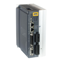
The following figure shows the name and location of the connectors.
Output Power - X1:
Motor Output
Break Relay
Input Power - X2:
External Regeneration
Control Power
Motor Power (Mains)
Motor Feedback - X6
Drive I/O - X5
Ethernet - X3, X4
Address Switches
Status Indicators LEDs
Auxiliary - X7
Torque Enable
Torque Enable Bypass
Power
Analog Inputs
*Optional 24VDC Control
Power
Hiperface DSL - X8
Figure 4. - IPA Connectors

Table of Contents

Related product manuals