Do you have a question about the Peak PCAN and is the answer not in the manual?
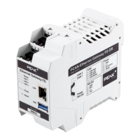
Details the hardware and software features of the PCAN-Ethernet Gateway FD DR.
Outlines the necessary voltage supply requirements before operating the device.
Lists the items included in the product package.
Describes the pin assignment and functionality of the two CAN interfaces.
Details the pin assignment for the RS-232 serial interface.
Explains the pin assignment for connecting the power supply.
Identifies the RJ-45 connector for network connectivity.
Describes the USB downstream port for connecting additional devices.
Explains the function and location of the device's reset button.
Details the LEDs used for indicating device status and power.
Guide to establishing the initial connection to the PCAN-Gateway for configuration.
Details on changing login data, setting up CAN channels, and connecting to a LAN network.
Instructions for mounting the PCAN-Gateway on a DIN rail and connecting it to the network.
Explanation of the LEDs used for device status, power, and LAN connectivity.
Procedures for rebooting and restoring the device using the reset button.
Information about the signal delay between CAN and LAN connections.
Overview of the web interface structure, including header and navigation elements.
Displays current device configuration, product information, and CAN interface status.
Information on defined routes and detected devices for message forwarding.
Details on creating and managing filters for CAN messages by ID.
Configuration and status of LAN and CAN network interfaces.
Displays detailed information about the PCAN-Gateway, including versions and configuration options.
Access to complete help information for the configuration website.
Useful links and contact information for PEAK-System Technik GmbH.
Example of forwarding message traffic from one CAN bus to another via a LAN network.
Example of forwarding message traffic between two CAN buses in both directions via LAN.
Configuration of filters to allow specific CAN IDs for outgoing messages in a Send route.
| Product Category | Gateway |
|---|---|
| CAN channels | 2 |
| CAN FD support | Yes |
| Ethernet | Yes |
| WiFi | No |
| Operating temperature | -40 to 85 °C |
| Interface | Ethernet |
| CAN Standard | CAN FD |