PCAN-Ethernet Gateway FD DR – User Manual
9
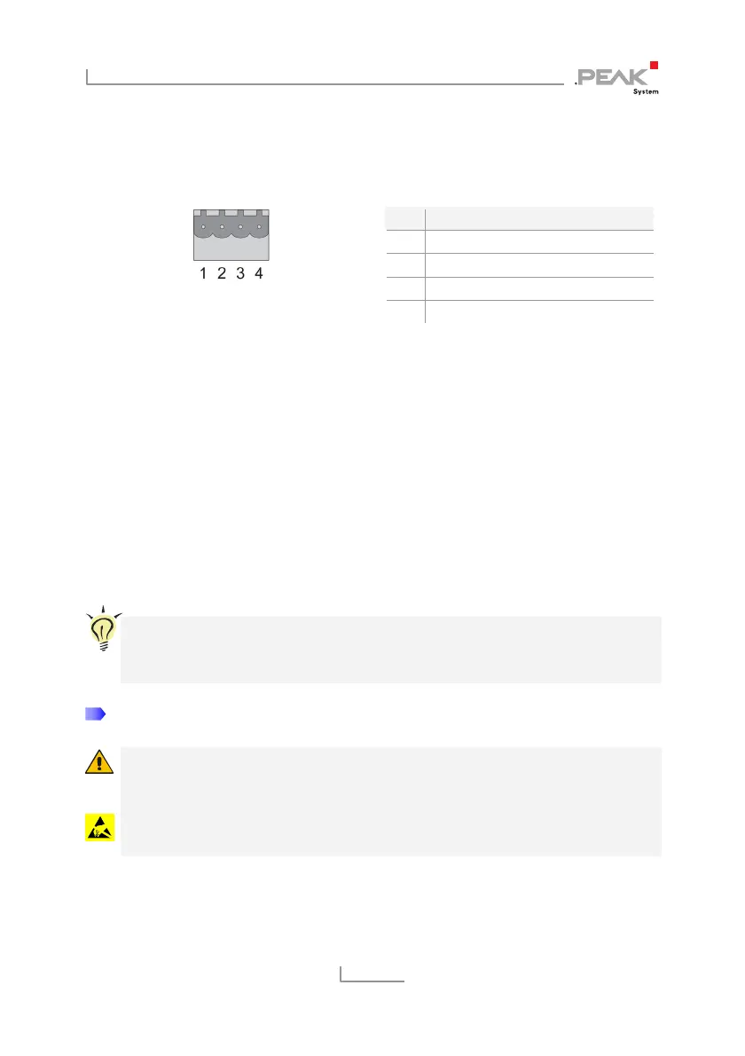
2.1 CAN1/CAN2
The CAN connectors are located on the upper side of the casing.
Figure 3: Pin assignment
CAN connector 1 + 2
Pin Function
1 CAN-High
2 CAN-Low
3 CAN-GND
4 CAN-Shield
The mating connectors (Phoenix Contact MSTB 2,5 / 4-ST BK -
1756298) are included in the scope of supply.
2.1.1 Activating the Internal Termination
A t
ermination of 120 Ohm can be activated for each CAN channel
via solder bridges on the board. A High-speed CAN bus (ISO
11898-2) must be terminated at both cable ends with 120 Ohm each,
otherwise interference will occur. The termination is not activated at
delivery.
Tip: We recommend adding termination at the CAN cabling, for
example with termination adapters (e.g. PCAN-Term). Thus,
CAN nodes can be flexibly connected to the bus.
Do the following to activate the internal CAN termination:
Risk of short circuit! Take great care when soldering to avoid
unwanted short circuits.
Attention! Electrostatic discharge (ESD) can damage or destroy
components on the card. Take precautions to avoid ESD.
1. Disconnect the power supply (Power).