PCAN-Ethernet Gateway FD DR – User Manual
10
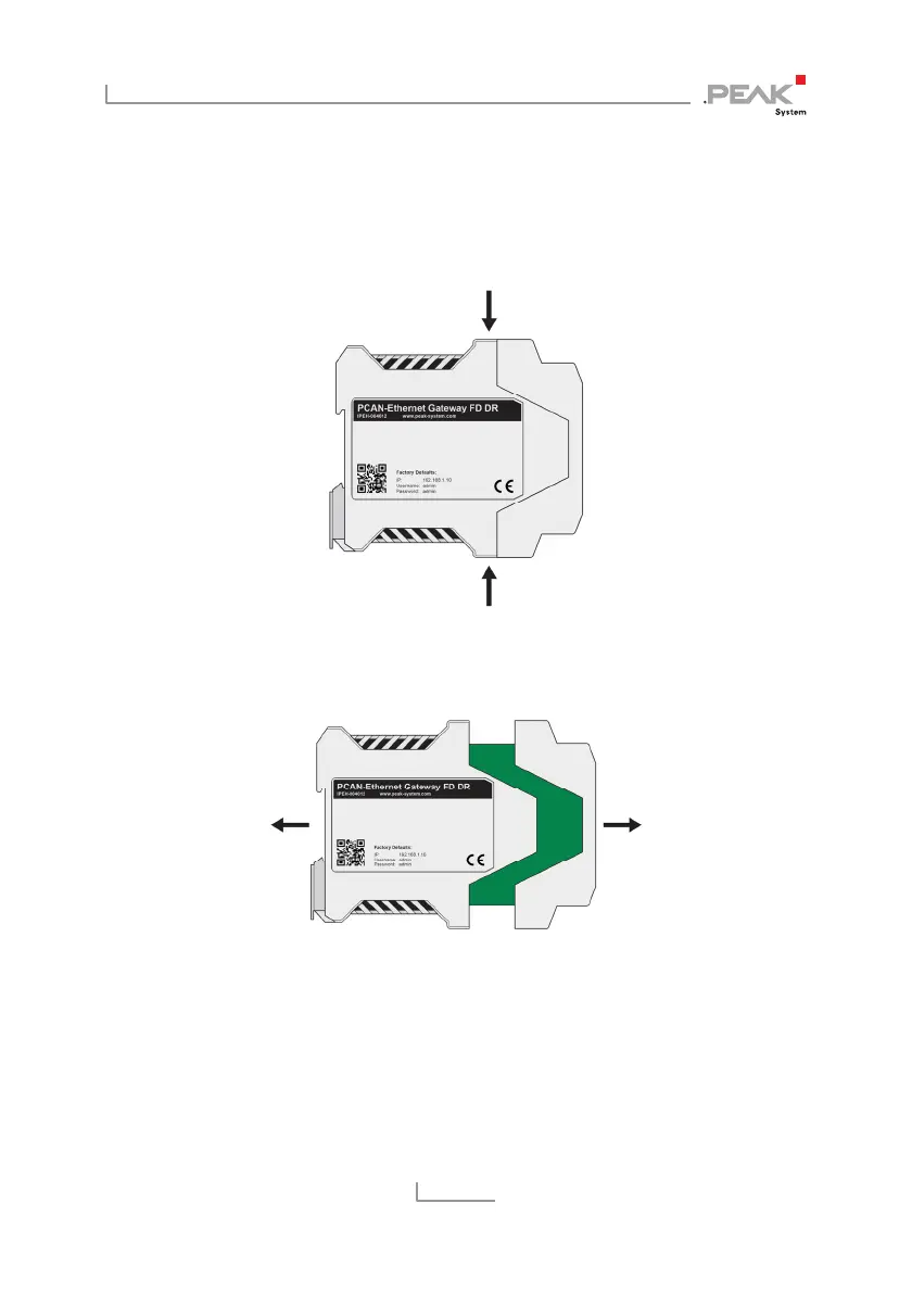
2. Use a screwdriver (or something similar) to press lightly
into the notches of the four snap locks on the top and
bottom of the housing.
The snap locks are unlocked.
Figure 4: Housing with the connection front on the right side
3. Pull the two casing sections apart.
Figure 5: Open housing with the back of the board
to activate the internal termination
4. Set the solder bridge(s) on the circuit board according to the
desired settings
Figure 6 shows the position of the solder fields.