PCAN-Ethernet Gateway FD DR – User Manual
11
The following table contains the possible settings.
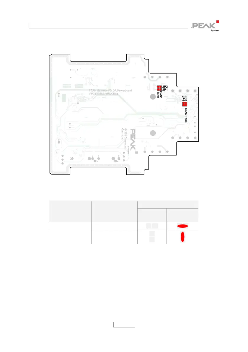
Figure 6: Bottom side of the power board with the solder fields
to activate the internal termination
Internal Termination
Connector Soldering Fields
Without
(standard)
Active
CAN 1 JP1 and JP2
CAN 2 JP3 and JP4
5. Re-insert the circuit board into the guide slot of the
counterpart of the housing and push both parts together
until the snap locks engage with a clicking sound.