PCAN-Ethernet Gateway FD DR – User Manual
12
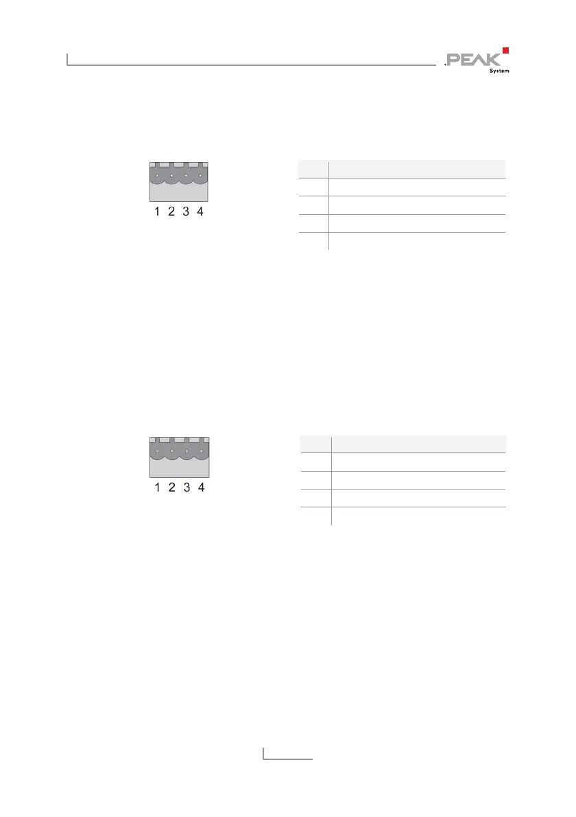
2.2 RS-232
The RS-232 connector is located on the lower side of the casing.
Figure 7: Pin assignment
RS-232 connector
Pin Function
1 GND
2 RxD
3 not connected
4 TxD
The mating connector (Phoenix Contact MSTB 2,5 / 4-ST BK -
1756298) is included in the scope of supply.
2.3 Power Supply
The connection for the power supply is located on the lower side of
the casing.
Figure 8: Pin assignment
Power connector
Pin Function
1 GND
2 not connected
3 Vbat (8 - 30 V)
4 Shield (top hat rail potential)
The mating connector (Phoenix Contact MSTB 2,5 / 4-ST BK -
1756298) is included in the scope of supply.
2.4 LAN
The RJ-45 connector for connecting to a LAN network is centered on
the front of the casing.