P350 Operation Manual 84
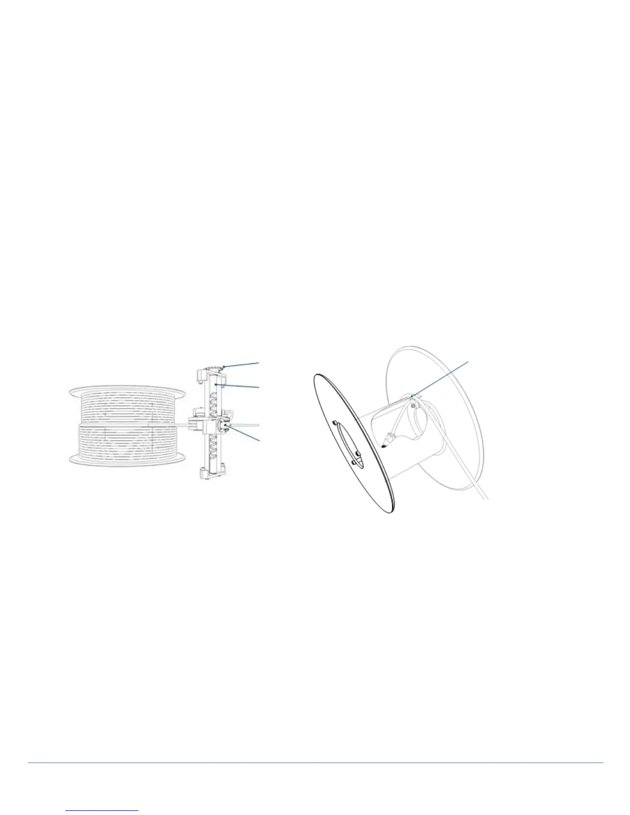
NOTE: Special care is required when threading the cable from the cable layering mechanism. You must correctly align
the cable mechanism to match the cable’s position on the drum otherwise the cable may become entangled. Proceed
as described below.
The cable layering mechanism (Level Wind) features a leadscrew that allows the layering mechanism to move in two
directions. When you retrieve the cable, this must be in-line with the follower (see Figure 9.7).
To synchronize the follower to the drive train and the cable, you may have to adjust the follower’s position manually.
To do so:
1. Slacken the 2-off internal M6x10 screws and move the chain tensioning block downwards (Figure 9.5).
2. Remove the level wind chain drive.
3. Adjust position of follower by turning the sprocket located at the leadscrew end so the follower is in-line with the
cable exiting the drum cassette.
4. Re-fit the level wind chain drive. Manually pull the cable from the drum and ensure that the follower moves in the
correct direction when the cable is spooling off the drum cassette. If this is not the case, remove the level wind chain
again and manually rotate the level wind sprocket (maintaining the same direction) until the follower has gone right to
the end of its travel and returned to the original position.
5. Re-attach the level wind chain drive, move the chain tensioning block upwards ensuring both chains are in tension
prior to fully tightening the 2-off M6x10 screws.
6. Replace both the drive & slave side panels.
Appendix 9.7: Cable layering sprocket and follower (left) Figure 9.8 Cable drum cassette (right)
Replacing cable
You can replace the cable in the cassette if required.
To do so (see Figure 9.4):
1. Disconnect the power and crawler from the system.
2. Pull the cable slowly out by hand.
3. Disassemble the system and remove the cable cassette following the guide in Section 9.4.
4. Remove the cassette’s strain relief clamp and remove the remaining part of the cable end.
5. Insert new cable end into the drum; allow 500mm slack when you re-fit the cable to the strain relief clamp on the
inside of the cassette.
6. Re-assemble the system using the procedure described in Section 9.4 ensuring the level wind follower (Figure
9.7) is in line with the entrance hole into the drum cassette.
7. Reconnect the power cable and switch on
8. Use manual drive mode to wind the cable back in to the drum.