23
INTELLIPRO
®
Variable Speed Pump Installation and User’s GuideINTELLIPRO
®
Variable Speed Pump Installation and User’s Guide
Alerts and Warnings
The IntelliPro
®
Variable Speed Pump displays all alarms
and warnings on the control panel display. When an alarm
or warning condition exists, the corresponding light will
be lit on the display.
Allcontrolpanelbuttonsaredisableduntilthealarmor
warningisacknowledgedwiththeEnterbutton.Pressthe
Resetbuttontoclearthealarmoncethefaultcondition
has been resolved.
Note: The pump will not start if the impeller is rotating.
Power Out Failure
Theincomingsupplyvoltageislessthan170VAC.
The drive faults to protect itself from over current. The
drivecontainscapacitorsthatkeepitpowereduplong
enough to save the current run parameters. If power is
restoredduringthisprocess,approximately20
seconds, the drive will not restart until completed.
Priming Error
If the pump is not dened as primed within the“Max
Priming Time” it will stop and generate a “Priming
Alarm”for10minutes,thenattempttoprimeagain.The
“Max PrimingTime” is set by the user on the priming
menu as discussed on page 14. If the pump cannot
prime within five attempts it will generate a permanent
alarm that must be manually reset.
Overheat Alert
Ifthedrivetemperaturegetsabove54.4°C(130°F)
the pump will slowly reduce speed until the over
temperature condition clears.
Anti-Freezing
Whenactive,themotorwillrunatthepresetRPMuntil
the drive temperature increases above the minimum. The
pump’s internal antifreeze protection is disabled when
connectedtoanautomationsystem.Freezeprotection
isprovidedbyselectingYESattheONWITHFREEZE
portion of the circuit function menu in the IntelliTouch
®
Control System. To re-enable the internal antifreeze
protection, the power to the drive must be cycled off
then backon.Important: See explanation of Anti-
Freeze mode on page 16.
Over Current
Indicated that the drive is overloaded or the motor has
anelectricalproblem.Thedrivewillrestart20seconds
after the over current condition clears.
Over Voltage
Indicates excessive supply voltage or an external
water source is causing the pump and motor to rotate
thereby generating an excessive voltage on the drives
internalDCbuss.Thedrivewillrestart20seconds
after the over voltage condition clears.
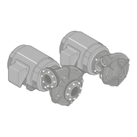
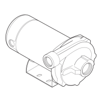
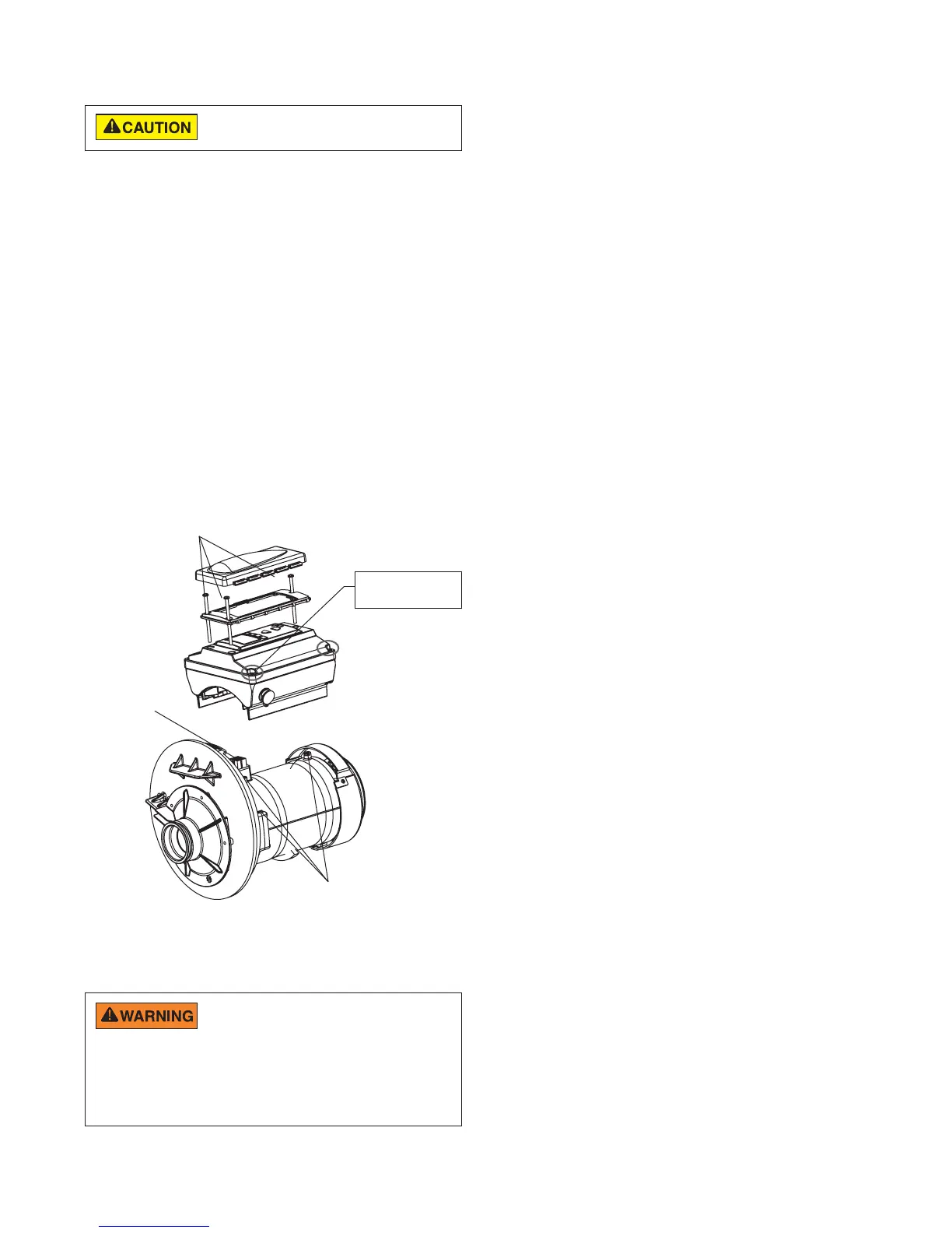
Drive Assembly Removal and Installation
To install the drive assembly onto the motor
assembly:
1. Be sure all electrical breakers and switches are
turned off before installing the drive.
2. Besurethatthegasketbetweenthedriveandmotor
isinplace.Itiscriticalinkeepingmoistureoutofthe
driveandmotor.Replacethegasketifdamaged.Do
notreassemblewithadamagedormissinggasket.
3. Verifythatthethree(3)orangemotorpostcapsare
in position before placing the drive on the motor
assembly(seeillustrationbelow).
4. Alignthedriveassemblywiththemotoradapterand
seat the drive on the motor assembly.
5. Secureandtightenthedriveassemblywiththethree
Phillips head screws.
DriveAssemblyandRemoval
Illustrated Parts View
FIRE and BURN HAZARD - The pump motor
may run at a high temperatures. To reduce the
risk of fire, do not allow leaves, debris, or foreign matter to collect
around the pump motor. To avoid burns when handling the motor, shut
off the motor and allow it to cool for 20 minutes before servicing. The
pump provides an automatic internal cutoff switch to protect the motor
from heat damage during operation.
Before installing this product, read and follow all
warning notices and instructions on page ii - iii.
Do not remove
these screws
PhillipsHead
Screw(3)
Adapter
Connector
andGasket
OrangeMotorPost
Caps(3)
 Loading...