108 KENR6933
Troubleshooting Section
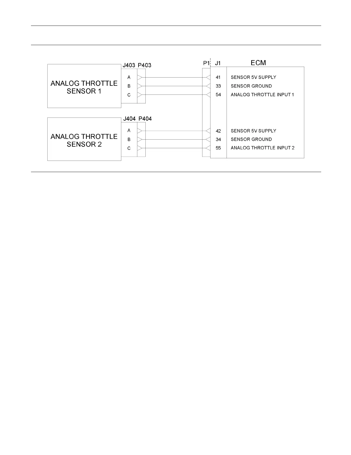
g01246557
Illustration 24
Typical example of the schematic for the P1 OEM connections for the analog throttle dem and sensors
Test Step 1. Check for Connector Damage
A. Turn the keyswitch to the OFF position.
B. Check the connectors and the harness for the
following faults:
•
Damage
•
Abrasion
•
Corrosion
•
Incorrect attachment
C. Refer to Troubleshooting, “Electrical Connectors
- Inspect”.
D. Perform a 45 N (10 lb) pull test on each of the
wires in the harness that are associated with
the throttle demand sensor. Check the wire
connectors at the following positions:
•
ECM
•
Pressure sensors
•
Throttle pedal
The wire connectors are shown in table 37 and
table 38.
E. Check the screws for the ECM connectors for the
correcttorqueof5.0N·m(44lbin).
Expected Result:
The connectors and the harness should be free of
the following faults: damage, abrasion, corrosion,
and incorrect attachment.
Results:
•
OK – Proceed to Test Step 2.
•
Not OK
Repair: Repair the connectors or the harness
and/or replace the connectors or the harness.
Use the electronic service tool in order to clear all
logged diagnostic codes and then verify that the
repair eliminates the fault.
STOP.
Test Step 2. Check for Active Diagnostic
Codes
A. Connect the electronic service tool to the
diagnostic connector.
B. Turn the keyswitch to the ON position.
C. Use the electronic service tool in order to monitor
the diagnostic codes. Check and record any active
diagnostic codes.
Note: Wait at least 15 seconds in order for the
diagnostic codes to become active.
 Loading...


