172 KENR6933
Troubleshooting Section
g01228375
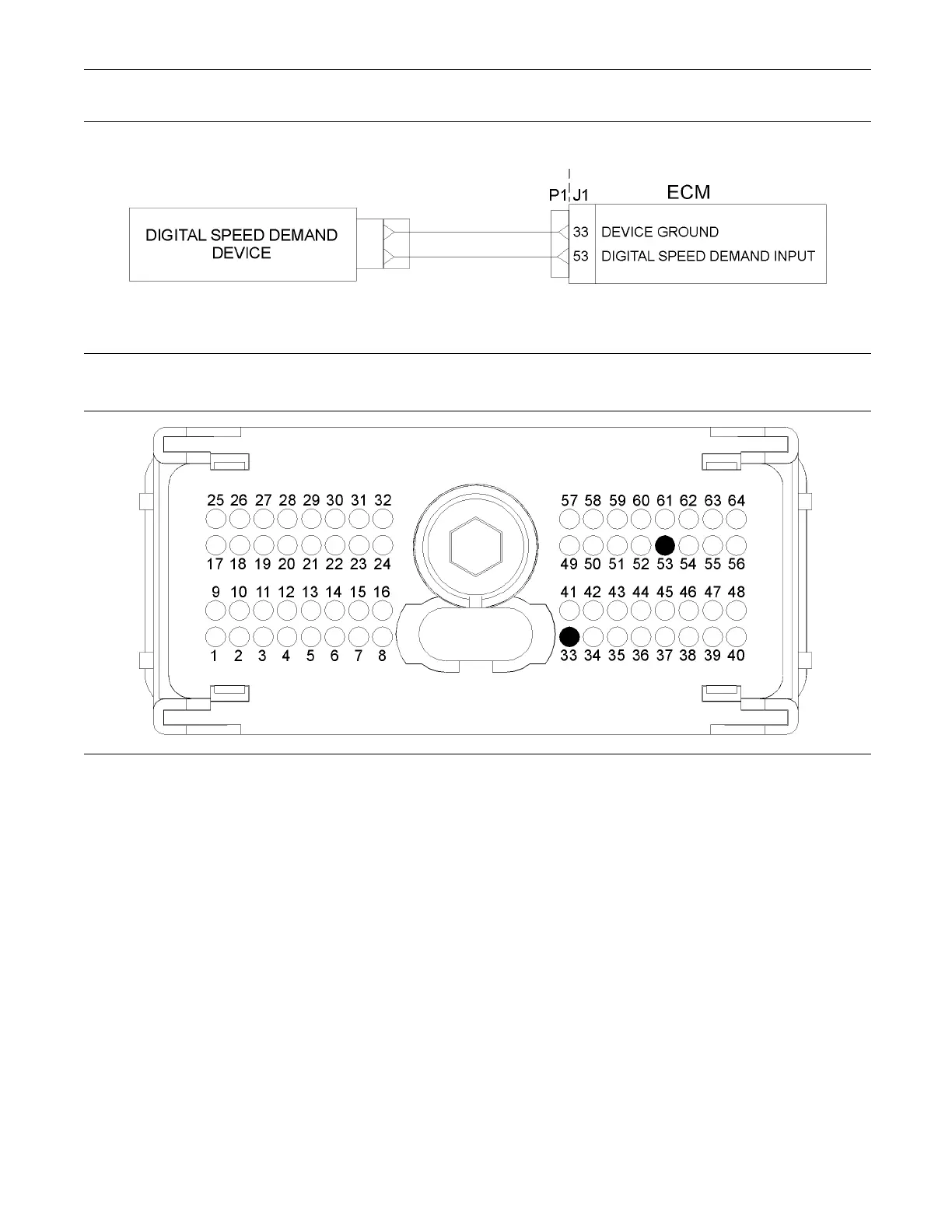
Illustration 67
Typical schematic of the digital speed demand device
g01228377
Illustration 68
Typical example of the pin locations on the P1 O EM connector
(33) Digital speed demand device return (53) Digital speed demand device input
Test Step 1. Insp ect Electrical Connectors
and Wiring
A. Inspect the P1/J1 connector, OEM harness and
the OEM connectors. Thoroughly inspect the
connector on the digital speed demand device.
Refer to Troubleshooting, “Electrical Connectors -
Inspect” for details.
B. Perform a 45 N (10 lb) pull test on each of the
wires in the ECM connector that are associated
with the digital speed demand device:
•
P1:33
•
P1:53
C. Check the screw for the ECM connector for the
correct torque of 5.0 N·m (44 lb in).
D. Check the harness for abrasion and pinch points
from the digital throttle position sensor to the ECM.
Expected Result:
All connectors, pins and sockets are completely
coupled and/or inserted and the harness is free of
corrosion, abrasion or pinch points.
Results:
•
OK – Proceed to Test Step 2.
•
Not OK