SEBU8603-01 25
Product Information Section
Model Views
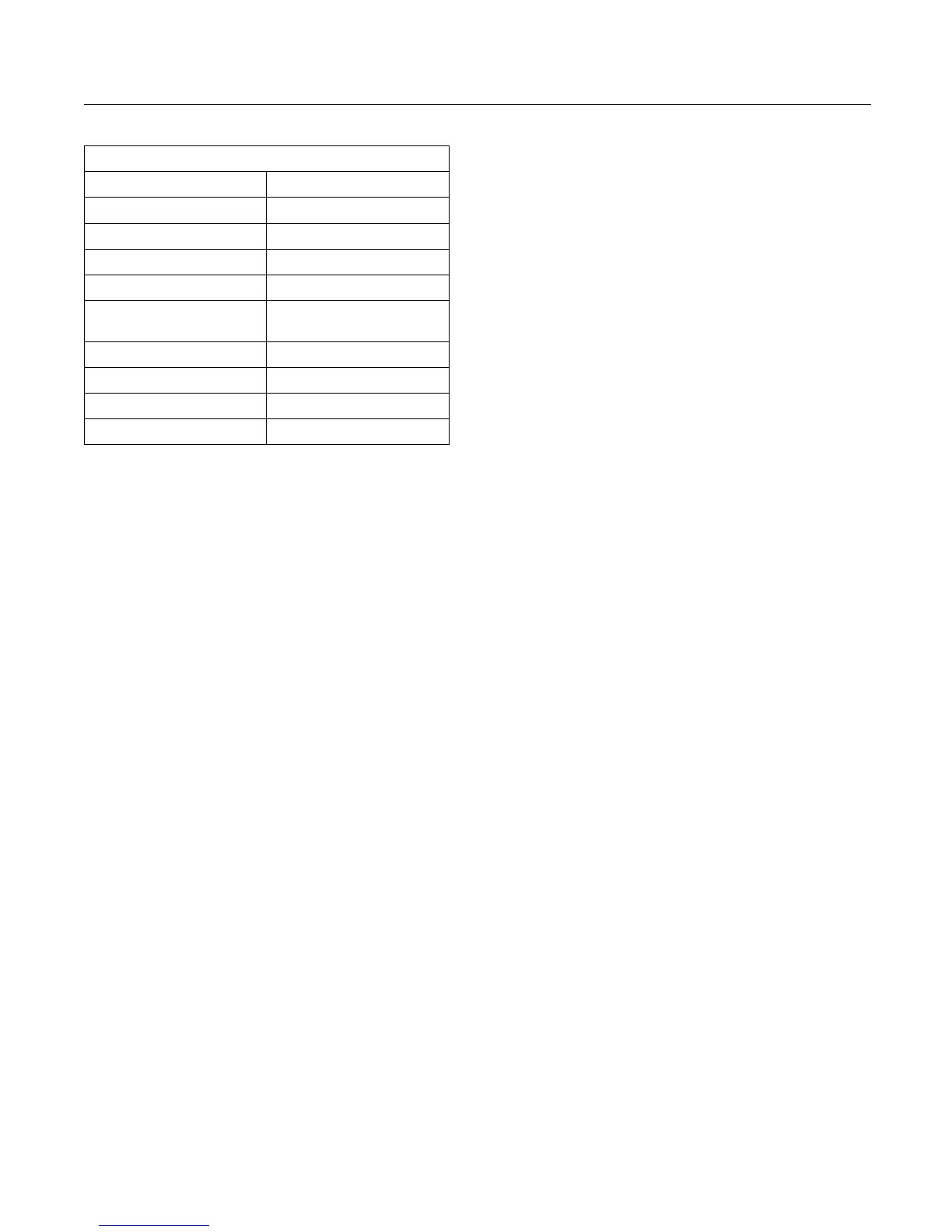
Table 1
Engine Specifications
Operating Range (rpm) 900 to 2800
(1)
Number of Cylinders 6 In-Line
Bore
105 mm (4.13
inch)
Stroke 127 mm (5 inch)
Power
129.4 kW (173.52 hp)
Aspiration Turbocharged charge
cooled
Compression Ratio 16.5:1
Displacement
6.6 L (402
.7 cubic inch)
Firing Order
1-5-3-6-2-4
Rotation (flywheel end) Counterclockwise
(1)
The operating rpm is dependent on the engine rating, the
application, and the configuration of the throttle.
Electronic Engine Features
The engine operating conditions are monitored.
The Electronic Control Module (ECM) controls the
response of the engine to these conditions and to
the demands of the operator. These conditions and
operator demands determine the precise control of
fuel injection by the ECM. The electronic engine
control system provides the following features:
•
Engine monitoring
•
Engine speed governing
•
Control of the injection pressure
•
Cold start strategy
•
Automatic air/fuel ratio control
•
Torque rise shaping
•
Injection timing control
•
System diagnostics
•
Low temperature regeneration
For more information on electronic engine features,
refer to the Operation and Maintenance Manual,
“Features and Controls” topic (Operation Section).
Engine Diagnostics
The engine has
built-in diagnostics in order to ensure
that the engine systems are functioning correctly. The
operator will be alerted to the condition by a “Stop or
Warning” lamp
. Under certain conditions, the engine
horsepower and the vehicle speed may be limited.
Theelectronicservicetoolmaybeusedtodisplay
the diagnost
ic codes.
There are three types of diagnostic codes: active,
logged, and
event.
Most of the diagnostic codes are logged and stored
in the ECM. F
or additional information, refer to
the Operation and Maintenance Manual, “Engine
Diagnostics” topic (Operation Section).
The ECM provides an electronic governor that
controls the injector output in order to maintain the
desired e
ngine rpm.
Engine Co
oling and Lubrication
The cooling system and lubrication system consists
of the fo
llowing components:
•
Gear-driven centrifugal water pump
•
W ater temperature regulator which regulates the
engine coolant temperature
•
Gear-driven rotor type oil pump
•
Oil coo
ler
The engine lubricating oil is supplied by a rotor type
oil pu
mp. The engine lubricating oil is cooled and the
engine lubricating oil is filtered. The bypass valve
can provide unrestricted flow of lubrication oil to
the en
gine if the oil filter element should become
plugged.
Engi
ne efficiency, efficiency of emission controls, and
engine performance depend on adherence to proper
operation and maintenance recommendations.
Engi
ne performance and efficiency also depend on
the use of recommended fuels, lubrication oils, and
coolants. Refer to this Operation and Maintenance
Man
ual, “Maintenance Interval Schedule” for more
information on maintenance items.
Aftertreatment System
Th
e aftertreatment system is approved for use by
Perkins. In order to be emission-compliant only the
approved Perkins aftertreatment system must be
us
ed on a Perkins engine.