permaPROC -1-
Outlets
1
3
2
4
5
6
Days
Weeks
Months
%Vol.
LC2500
Config.
Time PIN
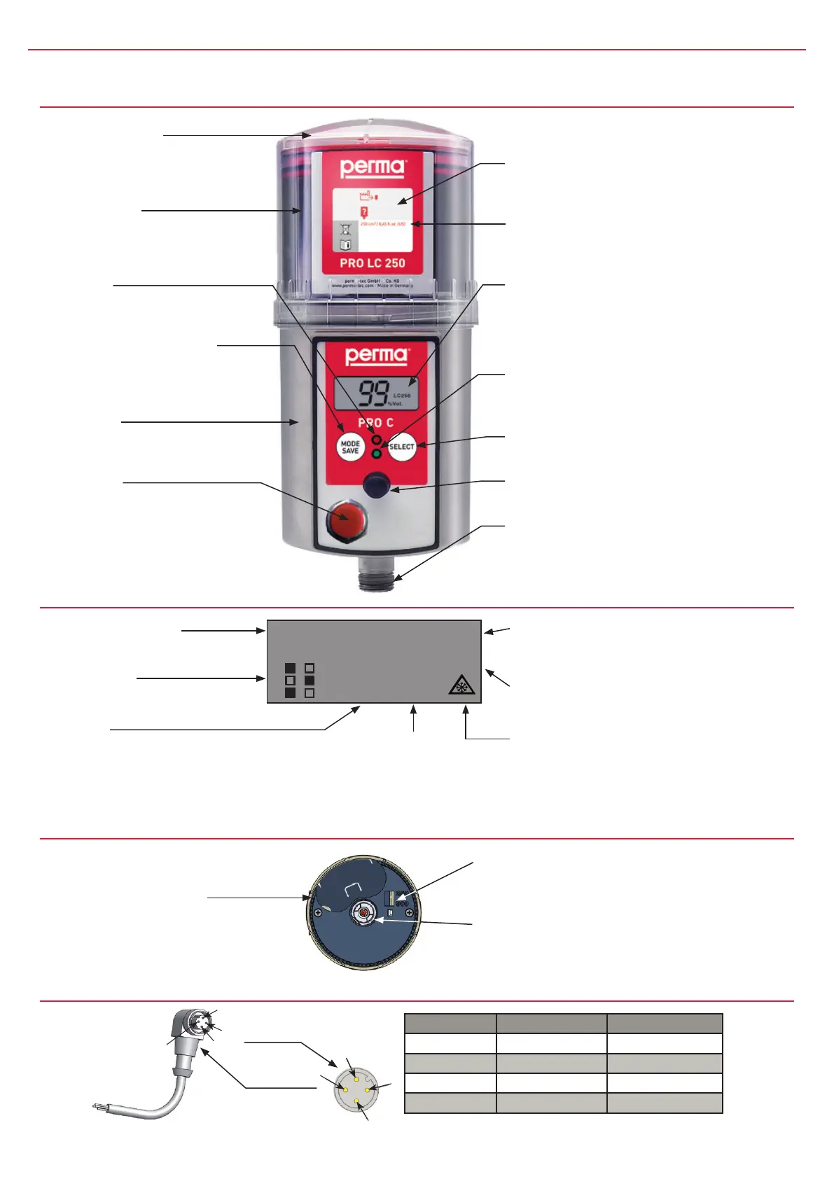
Lubrication System perma PRO C
Display
Con guration menu
Forenteringthesettings.
Outlets 1 - 6
Showsactivatedoutlets
Number
Showsremainingvolume,
dischargeperiod,outletno.,
PIN,andmalfunctioncodes.
Setting Mode
Displaysthecurrentsettingin
days,weeks,ormonths.
Size of PRO LC unit
DisplaysvolumeofLCunit
(250or500cm
3
)
Ice icon
Indicateseitherthatthetemperature
fellbelow0°C/32°F(iconblinking),
orthatthelowtemperatureshutoff
(below-20°C/-4°F)hasturnedthe
systemoff(iconpermanent).
Remaining volume
of the PRO LC unit
Showsthelubricant
remaininginthePRO
LCunitin%volume.
Protection cover
Withbayonetcatchfor
quickopening/closing.
PRO LC unit
(LubricationCanister)
Cartridge,piston,spindle
lledwithlubricant.
Red LED
Additionalmalfunction
indication.
Push Button: MODE/SAVE
LeadstotheCongurationMenu
andsavestheselectedsettings.
Drive Unit
Containselectronics,
motorandpumpsystem.
Connector
Usedforplugginginthe
connectingcablewhichconnects
thepermaPROCwiththecontrol
system(e.g.ofaPLC).
Content
Descriptionofthellingdateandthe
containedlubricant.
Type
Producttypeandsizeof
PROLCunit.
Display
Informsaboutoperatingconditions,
malfunctions,settingsandthe
lubricantvolumeleftinthe
PROLCunit.
Green LED
Additionalindicationofthecurrent
operatingcondition.
Push Button SELECT
Tochangesettings.
Connection f. distributor
PRO MP-6
Connection thread
G3/8forscrewingintoalubrication
pointorforconnectingalubricant
tube.
Drive Unit
Interlocking teeth
topositionthe
PROLCunit
No function! SettingofPROLCunit
sizeisdoneviamenuonthedisplay.
Catch
fordrivingthespindle.
Connecting Cable
1
2
4
3
1
2
4
3
Pin-number Strand color Function
1 brown Notassigned
2 white Malfunction
3 blue Ground
4 black Voltage
Pin assignment
oftheconnector
Pin assignment
ofcableconnector
Connecting cable
Forconnectingthe
lubricatortothe
controlsystem.