Adjustment
24V = 4% ED
-
-
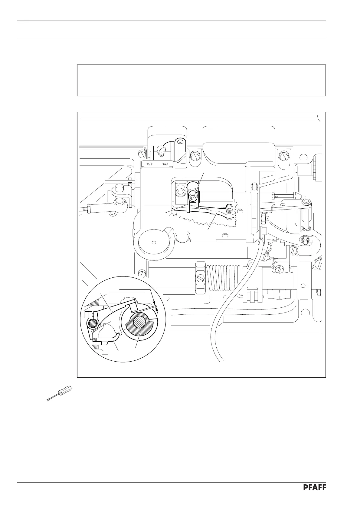
11.06.05 Release lever
Requirement
With the needle bar 2.0 after bdc (hole 1) there must be a clearance of 0.2 mm between
the roller of roller lever 1 and the base of control cam 2 with the engaging lever active.
Fig. 11 - 49
4
1
3
2
4
5
3
0.2 mm
● Position the needle bar 2.0 after bdc (hole 1).
● Activate engaging lever 3 manually.
● Press roller lever 1 down to the base of control cam 2.
● Position lever 4 on engaging lever 3 in such a way that there is a clearance of 0.2 mm
between roller lever 1 and the base of control cam 2. Lever 4 must be touching roller
lever 1 from the side.
● Tighten screw 5.
11 - 51