Adjustment
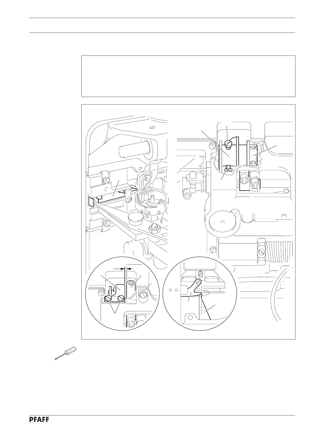
11.06.08 Control cam (final adjustment) and retaining spring
Requirement
1. with the end of thread guard 1 at the height of the right edge of bobbin case position
finger 2, thread catcher 3 must begin its forwards movement.
2. With the thread trimmer in resting position there must be a clearance of 0.5 mm
between retaining spring 7 and roller lever 8.
Fig. 11 - 52
-51
24V = 4% ED
9
8
7
1
2
5
5
4
6
3
0.5 mm
● Position the needle bar at bdc.
● Activate the engaging lever.
● Loosen screws 5.
● Move control cam 4 in accordance with requirement 1 and position retaining collar 6 so
that it is touching.
● Tighten screws 5.
● Fit retaining spring 7 together with the cover and tighten screws 9 lightly.
● Push retaining spring 7 upwards as far as possible and align it in accordance with requirement 2.
● Tighten screws 9.
11 - 54