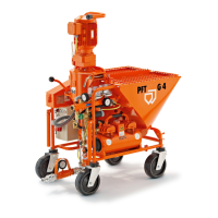
Mixing Pump PFT G4
Structure and function
2007-09-05 27
Control panel:
1 Selector switch cellular wheel
Manual-0-Automatic
2 Selector switch water pump
Manual-0-Automatic
3 Indicator light "sense of rotation"
4 Main reverse switch,
is concurrently an Emergency-Stop
switch
5 Indicator light red, motor protection
switch tripped
6 Button "water flow"
7 Illuminated button "operation ON"
8 Button "operation OFF"
9 Button "sense of rotation reverse"
10 Main current connection 32 A
11 Remote control socket
12 Dummy plug 4-pin
13 CEE – attachment socket 4x32 A
gear motor
14 CEE – attachment socket 4x16 A
air compressor
Fig. 10: Control panel