Mixing Pump PFT G4
Operation
2007-09-05 49
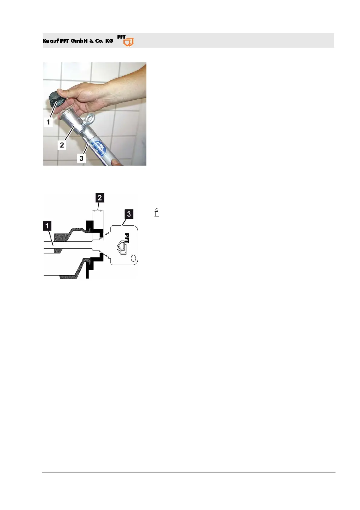
Fig. 50: Air nozzle pipe and plaster nozzle
25. Remove air nozzle pipe (Fig. 50/3) and fine plaster nozzle
(Fig. 50/1) from the sprayer (Fig. 50/2).
26. Open the water removal valve until the sponge ball escapes at
the fine plaster device. Repeat this process until the hose is
clean.
27. If there are different hose diameters then the hoses must be
cleaned separately with the appropriate sponge balls.
28. If there is heavier fouling repeat this process.
29. Knock the air nozzle pipe (Fig. 50/3) free with the rasp.
30. Switch on the compressor and blow out the air nozzle pipe.
Adjust the air nozzle pipe clearance
Fig. 51: Air nozzle pipe clearance
31. Use the supplied gauge (Fig. 51/3) to correctly adjust the air
nozzle pipe distance (Fig. 51/2).
The distance between air nozzle pipe and plaster nozzle must
correspond to the hole diameter of the plaster nozzle; for
example: 14 mm (0.55 inch) fine plaster nozzle = distance of
14 mm (0.55 inch).
32. Switch off the machine (main switch on position "O").
Pos: 6.21 /KN2006-SM/nL.......... Seitenumbruch .......... @ 8\mod_1141998334703_0.doc @ 293764