Communications interface
B-3
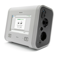
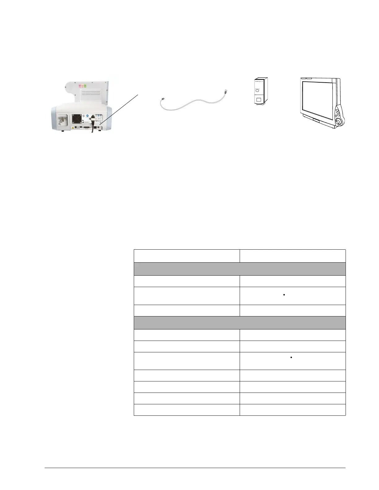
Figure B-3: Connection from ventilator to Philips patient monitor
Data display
The data from your Respironics V60/V60 Plus Ventilator is displayed in several
windows on your Philips monitor. This data may be labeled differently on the
monitor than on the ventilator. Refer to Table B-1 to interpret these labels.
For more information, consult the documentation for your IntelliBridge or
VueLink module and patient monitor.
.
Philips patient monitor
IntelliBridge EC10 module
PN 865115 A01 or
VueLink module
PN M1032-A02
IntelliBridge interface cable
(Part of EC5 module) or
VueLink interface cable
PN M1032-61654
EC5 module
PN 865114
Option #105
(for EC10 only)
Table B-1: Ventilator data displayed on Philips monitor
Monitor label Ventilator label
Waveform
AWP P (airway pressure)
AWF
V
E
(flow)
AWV V (volume)
Monitored parameters
%Bsp:t Pt. Trigger
Leak Pt. Leak or Tot.Leak
MINVOL
V
E
PIP PIP
RRaw Rate
Tin/Tt T
I
/T
TOT
TVexp V
T