Communications interface
B-5
Remote alarm port WARNING: To prevent possible patient injury due to nonannunciating alarms, verify
the operation of any remote alarm device before use.
WARNING: To ensure the functionality of the remote alarm, connect only Respironics-
approved cables to the remote alarm port.
CAUTION: The remote alarm port is intended to connect only to an SELV (safety
extra-low voltage and ungrounded system with basic insulation to
ground), in accordance with IEC 60601-1. To prevent damage to the
remote alarm, make sure the signal input does not exceed the
maximum rating of 24 VAC or 36 VDC at 500 mA with a minimum
current of 1 mA.
NOTE: Selecting Alarm Silence deactivates the remote alarm.
The remote alarm (nurse call) port allows ventilator alarm conditions to be
annunciated at locations away from the ventilator (for example, when the
ventilator is in an isolation room). The ventilator sends alarm signals to a
remote alarm through the connector at the rear of the ventilator (Figure B-1 on
page B-1). Figure B-4 shows the pin assignments for this connector. The
connector is a standard ¼-inch, female, audio (ring, tip, sleeve) connector.
The ventilator signals an alarm using either a normally open (NO) or normally
closed (NC) relay contact. The de-energized state of the relay represents an
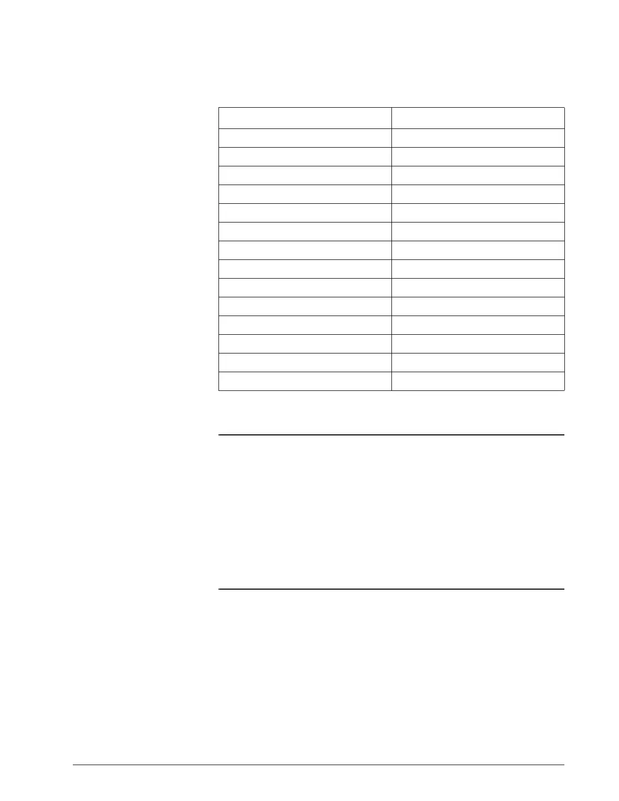
LOW EXH MV Low Minute Ventilation
LOW O2 SUPPLY Low O
2
Supply Pressure
LOW RESP RATE Low Rate
LOW EXH TV Low Tidal Volume
NO O2 SUPPLY Oxygen Not Available
OCCLUSION Patient Circuit Occluded
PT. DISCONNECT Patient Disconnect
PPV MAX P PPV Max P
PPV MAX V PPV Max V
PRESS REG HIGH Pressure Regulation High
PROX DISCONNECT Proximal Pressure Line Disconnect
Vent CHK DEVICE Check Vent:
VENT ON BATTERY Running on Internal Battery
Ventilation parameters blanked Vent Inoperative xxxx
Table B-1: Ventilator data displayed on Philips monitor (continued)
Monitor label Ventilator label