General information
3-7
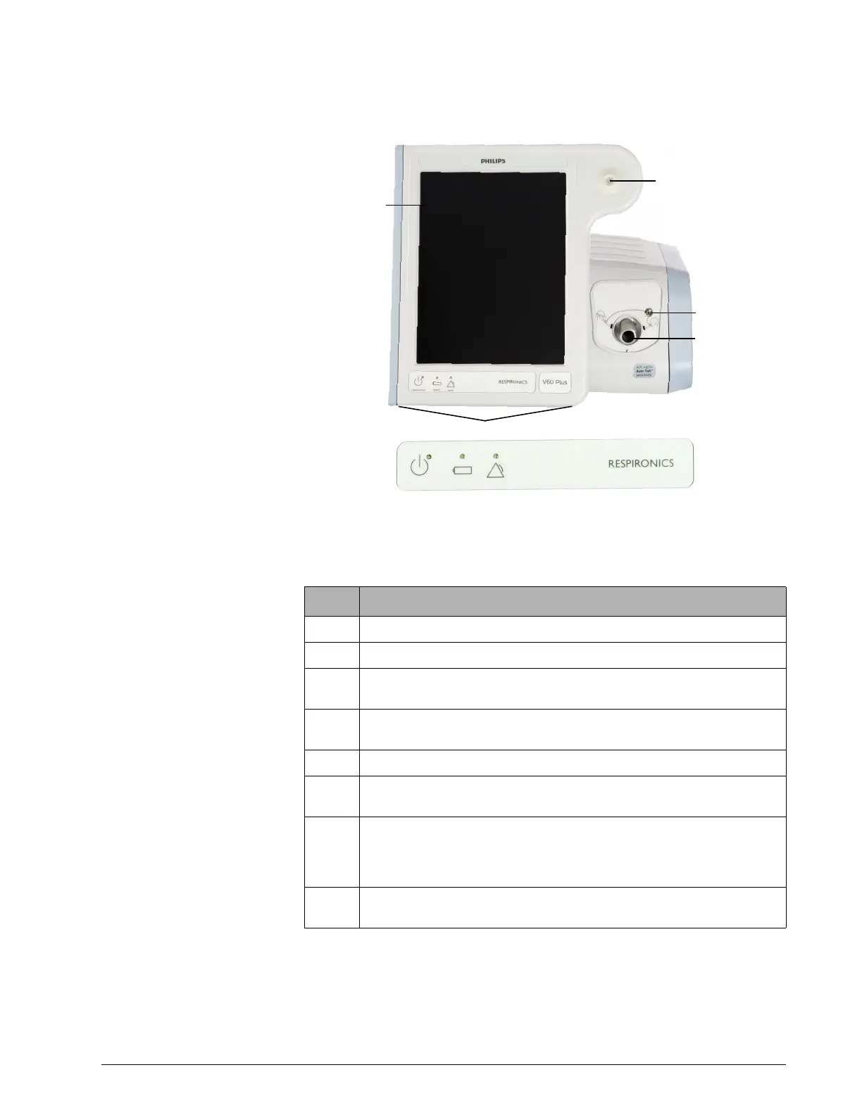
Figure 3-3: Front view
Number Description
1 Graphical user interface. Color LCD (liquid crystal display) with touchscreen.
2 Accept button. Activates selections.
3 Proximal pressure port. Connection for tubing that monitors patient pressure in
the patient circuit.
4 Ventilator outlet (To patient) port. Main connection for the patient circuit. Deliv-
ers air and oxygen in prescribed pressures to the patient.
5 Alarm speakers (beneath ventilator)
6 Alarm LED. Flashes during a high-priority alarm. On continuously during a venti-
lator inoperative condition.
7 Battery (charged) LED. Flashes when battery is charging. On continuously when
battery is charged. Off when ventilator is running on battery, when a battery er-
ror or failure is detected, or when the ventilator is off and AC power is not con-
nected.
8 ON/Shutdown key with LED. Turns on AC power and initiates ventilator shutdown.
LED is continuously on when AC power is connected.