FL SWITCH 2000 / FL NAT 2000
14 / 226
PHOENIX CONTACT 108997_en_04
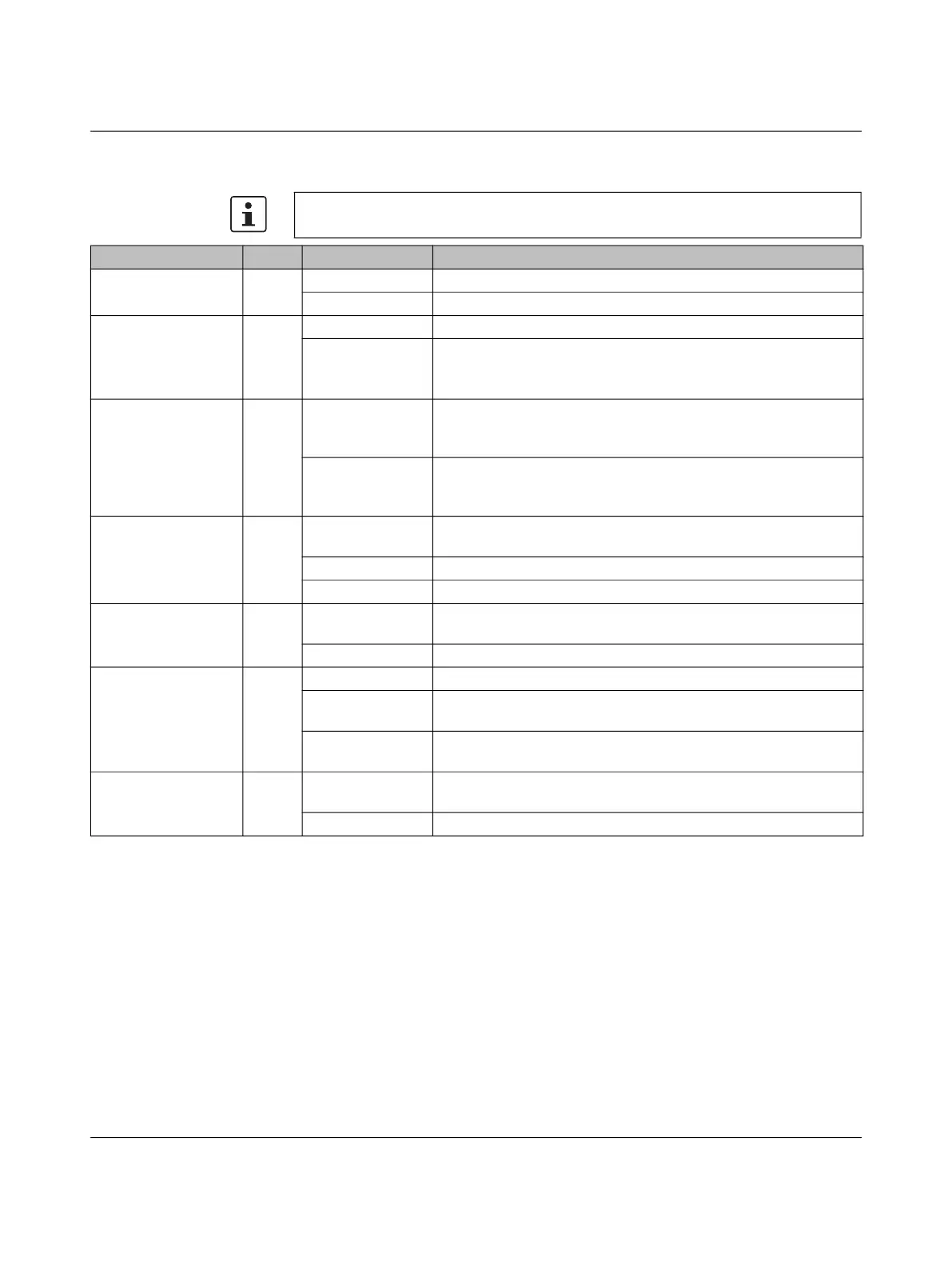
2.3 Status and diagnostic indicators
Please note that the meaning of the LEDs differs in Smart mode (see “Using Smart mode”
on page 43).
Des. Color Status Meaning
US1 Green On Supply voltage 1 within the tolerance range
Off Supply voltage 1 too low
US2
(for 22xx/23xx/24xx/
25xx/26xx/27xx
versions only)
Green On Supply voltage 2 within the tolerance range
Off Supply voltage 2 too low
FAIL
1
(for 22xx/23xx/24xx/
25xx/26xx/27xx
versions only)
Red On An error has occurred.
The digital alarm output (22xx/23xx versions) is floated, the signal
contact (24xx/25xx versions) is closed.
Off No error. The digital alarm output (22xx/23xx versions) is connected
to ground potential (ground), the signal contact (24xx/25xx versions)
is open.
LNK/ACT
2
Green/
orange
On Green: link active
Orange: SFP link at combo port active
Flashing Data transmission
Off Link not active
SPD
2
Green/
orange
On Green: 100 Mbps
Orange: 1000 Mbps (for 21xx/23xx/25xx/27xx versions only)
Off 10 Mbps if Link LED is active
BF
(for PN versions only)
Red On The device does not have an active link
Flashing The device has at least one active link but no active PROFINET
connection
Off The device has at least one active link and at least one active
PROFINET connection
SF
(for PN versions only)
Red On A PROFINET alarm is present and was reported to the control
system
Off No PROFINET alarm is present
1
The 26xx/27xx and 2500/K1 versions do not feature an alarm output/signal contact.
Only the FAIL LED indicates a pre-defined error.
2
20xx/20xxF/21xx/22xx/23xx/26xx/27xx versions:
The LNK/ACT LED is located directly at the top of the port. The SPD LED is always located at the bottom of the port.
24xx/25xx versions: The LEDs are located on the front of the device.
 Loading...