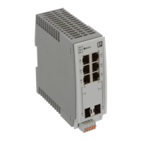
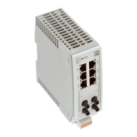
FL SWITCH 2000 / FL NAT 2000
38 / 226
PHOENIX CONTACT 108997_en_04
3.5.4 Installing the devices
3.5.4.1 Tightening torques for M12 connectors and cover cap
To prevent leakage and damage to the connectors or the device, observe the tightening
torques when installing M12 connectors with standard screw connection. The recom-
mended tightening torque is 0.4 Nm.
The recommended tightening torque for the M16 cover cap of the Smart mode button and
microSD slots is 1.2 Nm; it should not exceed 4 Nm.
3.5.4.2 Connecting the 24 V DC supply voltage
You can use M12 connectors with standard screw connection or M12 push-pull connectors
from Phoenix Contact.
• Use the XD1 socket for the power supply of the device.
Cover unused M12 ports with filler plugs to ensure that the housing is sealed tight. This
applies to the supply voltage connections as well as to the Ethernet ports.
After using the Smart mode button or the microSD slot, always install the M16 cover cap.
This is the only way to ensure effective tightness of the device.
For the standard 26xx/27xx versions, power is supplied via an A-coded M12 connector.
For the 26xx PN/27xx PN PROFINET versions, power is supplied via an L-coded M12
connector.
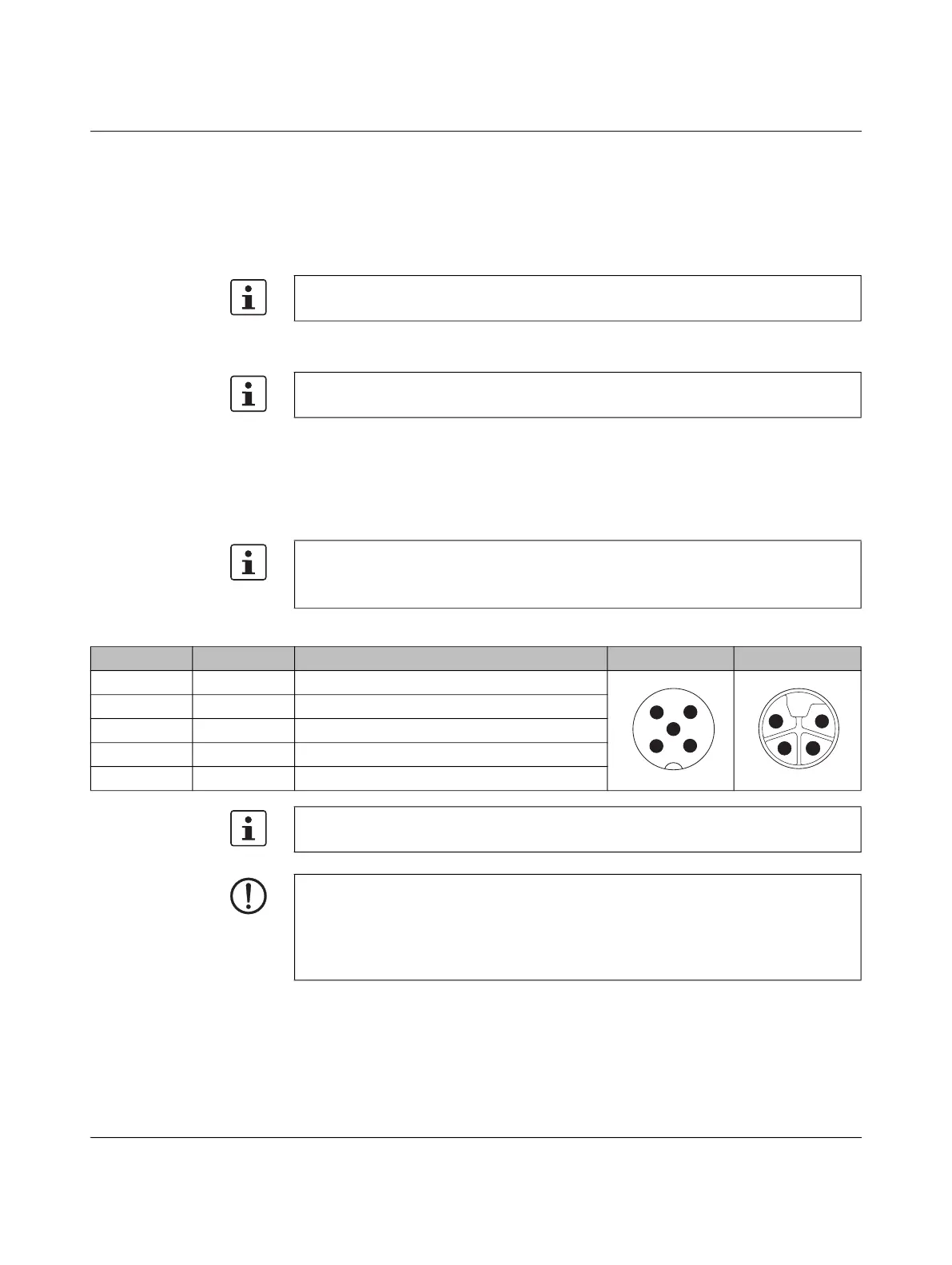
Table 3-13 Pin assignment for the power supply via M12 connectors with marking “XD1”
Pin number Abbreviation Description A-coding L-coding
1 US1 Power supply 1
2 GND Ground
3 GND Ground
4 US2 Power supply 2
5 FE Functional ground
The figure only shows the pin assignment of the connector but does not give information
on the mechanical alignment during installation.
NOTE: Data corruption or loss
To ensure immunity when using L-coded connectors (PROFINET versions), implement
the FE connection via mounting screws and a connection to the metal housing.
When using A-coded connectors, you can implement the FE connection via pin 5 or via
the mounting screws.
 Loading...