Mounting and installation
108997_en_04 PHOENIX CONTACT 39 / 226
Supplying other devices with power
The 26xx/27xx versions allow for supplying other devices with power. This way, you can im-
plement efficient cabling concepts.
• Connect the cable for the outgoing supply voltage to socket XD2.
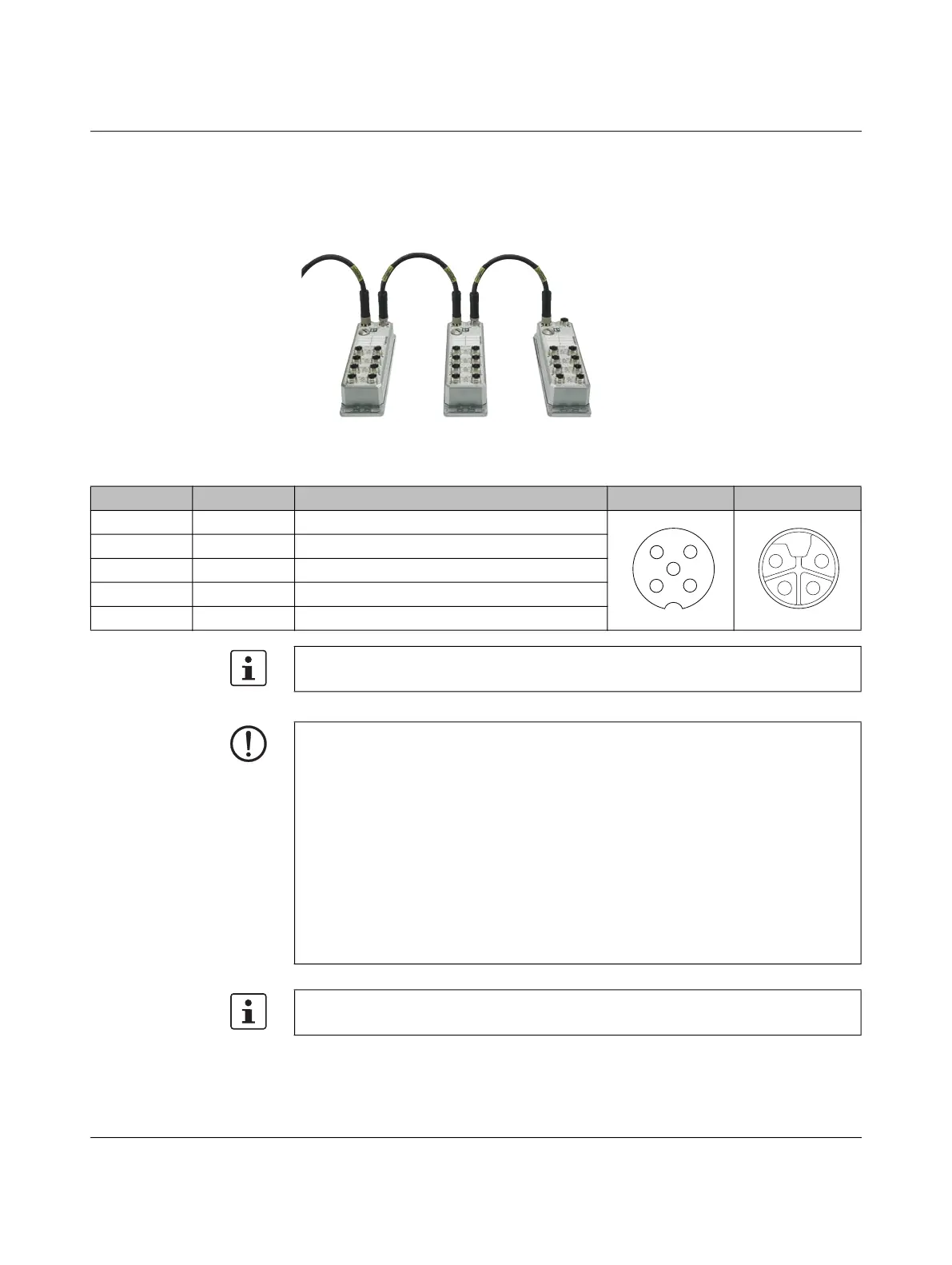
Figure 325 Efficient power supply
Table 3-14 Pin assignment for the power supply via M12 connectors with marking “XD2”
Pin number Abbreviation Description A-coding L-coding
1 US1 Power supply 1
2 GND Ground
3 GND Ground
4 US2 Power supply 2
5 FE Functional ground
The figure only shows the pin assignment of the connector but does not give information
on the mechanical alignment during installation.
NOTE: Risk of damage to electronics
The current carrying capacity per contact (US1/US2) of the A-coded M12 connectors is
4 A. The total current of US1 and US2 must not exceed 8 A.
The current carrying capacity per contact (US1/US2) of the L-coded M12 connectors is
16 A. The total current of US1 and US2 must not exceed 20 A.
Make sure these values are not exceeded and take into consideration the current con-
sumption of the switch.
Please note: The connection for the outgoing supply voltage is not monitored for over-
load. Ensure fuse protection for the power supply that is suitable for your design.
If the permissible current carrying capacity is exceeded, this may result in damage to the
connectors, the electronic components, and to the PCB of the device.
We recommend using pre-assembled cables.
 Loading...