FL SWITCH 2000 / FL NAT 2000
34 / 226
PHOENIX CONTACT 108997_en_04
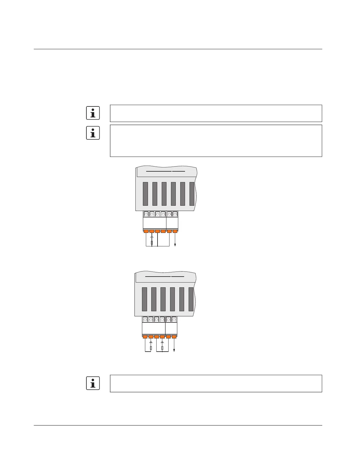
3.4.4.2 Connecting the 24 V DC supply voltage
The device is operated using a 24 V DC voltage, which is applied via COMBICON connec-
tors. The voltage can be supplied redundantly.
The module is designed exclusively for operation with safety extra-low voltage
(SELV/PELV). In redundant operation, both power supplies must satisfy the requirements
of the safety extra-low voltage.
Figure 319 Supplying the switch using one voltage source
Redundant 24 V DC supply
Figure 320 Supplying the switch using two voltage sources
The 25xx/K1 versions do not feature a signal contact. Therefore, the 2-pos. COMBICON
connector with the marking XG1 is not required (see Figure 319 and Figure 320).
If redundant power supply monitoring is active (default setting), an error is indicated if only
one voltage is applied.
A bridge between US1 and US2 prevents this error message. It is possible to deactivate
monitoring in web-based management or via SNMP.
11
2234
US1 F1
XG1
US2GND
XD1
F2GND
+
24 V DC OUT
In order to reset the switch on power up, the power supply must be interrupted for at least
three seconds.
11
2234
US1 F1
XG1
US2GND
XD1
F2GND
++
24 V DC OUT
 Loading...