Mounting and installation
108997_en_04 PHOENIX CONTACT 25 / 226
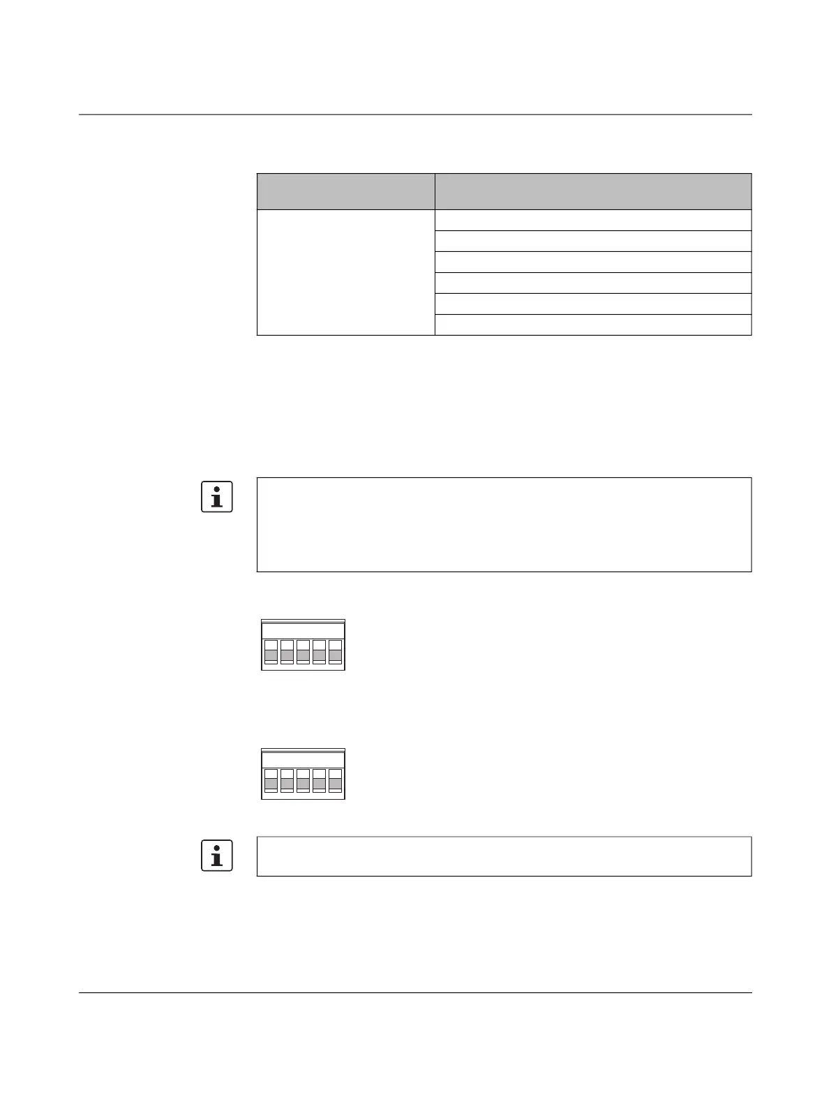
3.2.4.2 Connecting the supply voltage
The device is operated using a 24 V DC voltage, which is applied via COMBICON connec-
tors. For the 22xx/23xx device versions, you can supply the voltage redundantly (see
Figure 37).
The module is designed exclusively for operation with safety extra-low voltage
(SELV/PELV). In redundant operation, both power supplies must satisfy the requirements
of the safety extra-low voltage.
Figure 36 Operating the device with one power supply (example)
Figure 37 Redundant operation with two power supplies (example)
Table 3-6 Specifications for ferrules
Recommended crimping
tool
1212034 CRIMPFOX 6
Ferrules without insulating
collar, in accordance with
DIN 46228-1
Cross-section: 0.25 mm
2
; Length: 7 mm
Cross-section: 0.34 mm
2
; Length: 7 mm
Cross-section: 0.5 mm
2
; Length: 8 mm … 10 mm
Cross-section: 0.75 mm
2
; Length: 8 mm … 10 mm
Cross-section: 1 mm
2
; Length: 8 mm … 10 mm
Cross-section: 1.5 mm
2
; Length: 10 mm
For 22xx/23xx device versions:
If redundant power supply monitoring is active (default setting), an error is indicated if only
one voltage is applied.
A bridge between US1 and US2 prevents this error message. It is possible to deactivate
monitoring in web-based management or via SNMP.
Please note that load distribution does not take place. The power supply unit with the
higher voltage will supply the device on its own.
 Loading...