Mounting and installation
108997_en_04 PHOENIX CONTACT 31 / 226
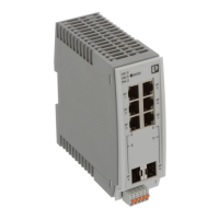
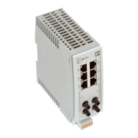
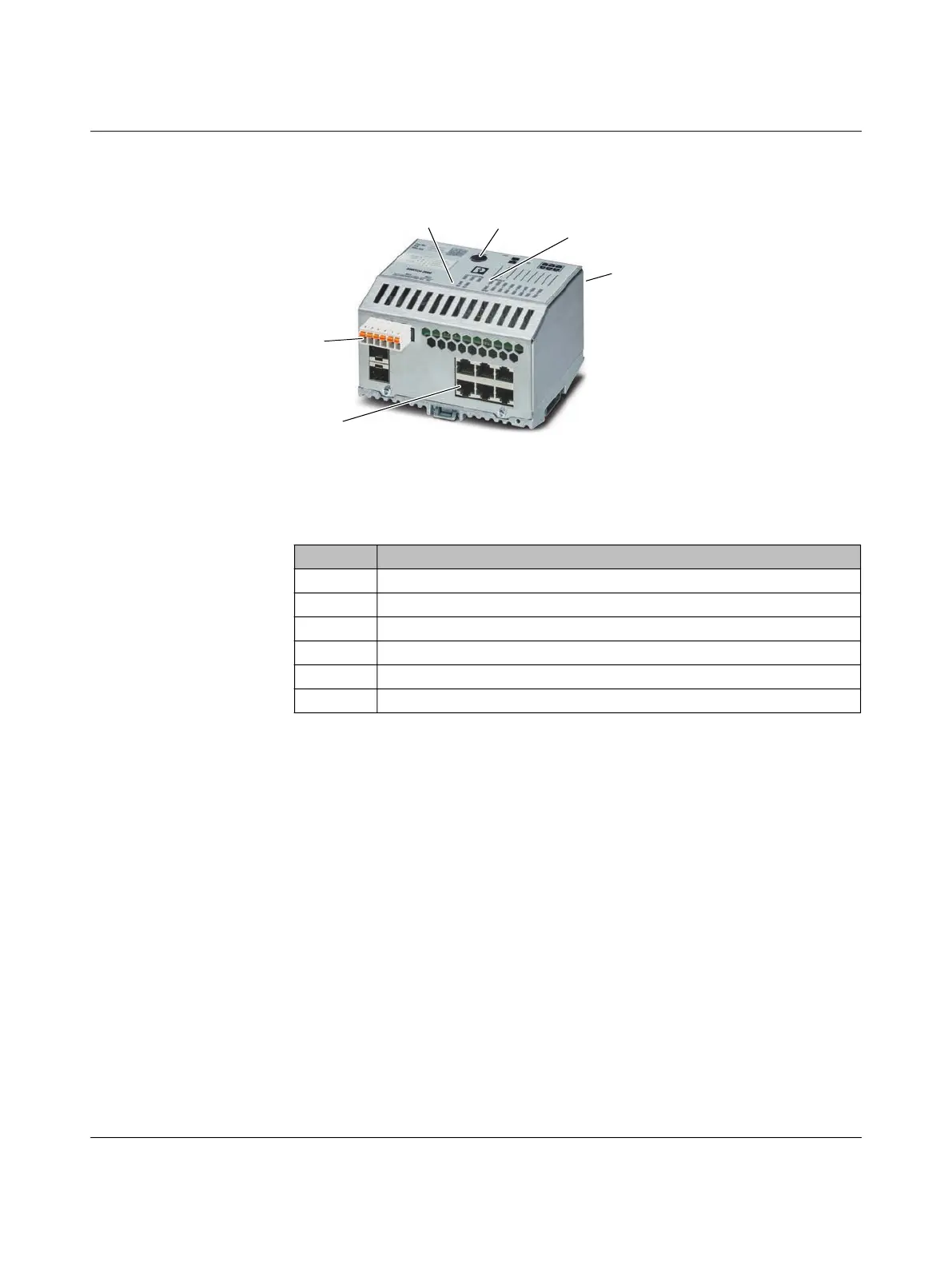
3.4.2 Elements of the devices
Figure 316 Elements of the FL SWITCH 24xx/25xx devices
3.4.3 Mounting and removing the devices
Mount the device on a clean, horizontally installed DIN rail in accordance with
DIN EN 50022 (e.g., NS 35 ... from Phoenix Contact). To avoid contact resistance, only use
clean, corrosion-free DIN rails. End brackets (E/NS 35 N, Order No. 0800886) can be
mounted to the right and left of the device to stop the modules from slipping on the DIN rail.
To allow air to circulate freely, the vents must not be covered. A clearance of 30 mm to the
vents of the housing is recommended. The control cabinet/box must meet the requirements
of EN 60950-1:2006 with respect to fire protection enclosure.
The IP20 degree of protection (IEC 60529/EN 60529) of the device is intended for use in a
clean and dry environment. Do not subject the device to mechanical and/or thermal stress
that exceeds the specified limits.
Table 3-10 Key for FL SWITCH 24xx/25xx
Number Meaning
1 Connection of the supply voltage
2 RJ45 ports
3 PROFINET status LEDs (for PN versions only)
4 Smart mode button
5 Diagnostic and status indicators
6 Slot for optional SD card
4
1
6
5
2
3
 Loading...