Mounting and installation
108997_en_04 PHOENIX CONTACT 35 / 226
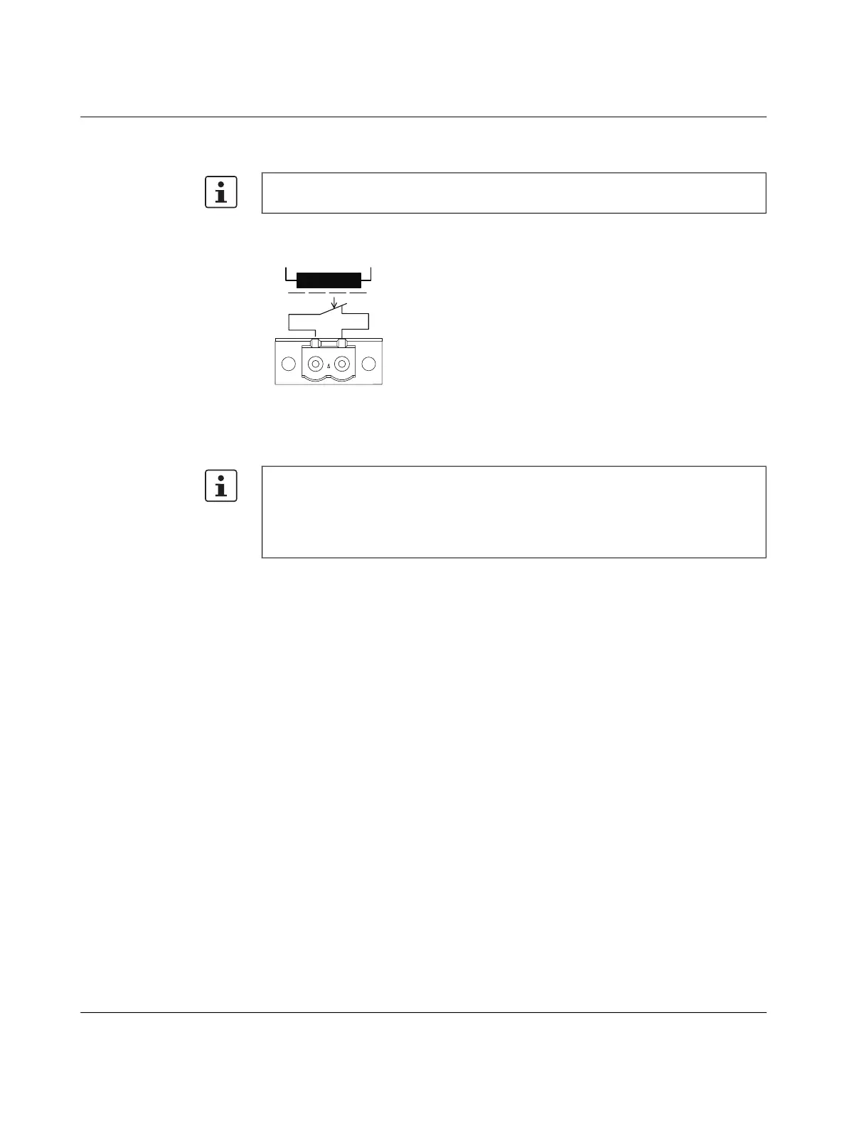
3.4.4.3 Signal contact
The switch has a floating signal contact. An error is indicated when the contact is opened.
Figure 321 Basic circuit diagram for the signal contact
The indicated error states are configured in web-based management or via SNMP.
The 25xx/K1 versions do not feature a signal contact.
In the event of non-redundant voltage supply, the switch indicates the failure of a supply
voltage by opening the signal contact.
This error message can be prevented by connecting the supply voltage to both US1/US2
terminal blocks in parallel (as shown in Figure 319) or by deactivating redundant power
supply monitoring in web-based management or via SNMP.
 Loading...