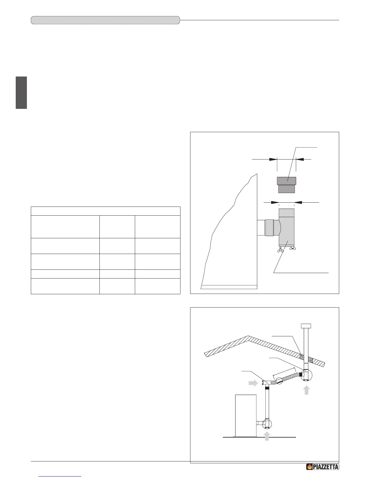
Ø100mm
Ø80mm
STRAIGHT REDUCER
Ø80>Ø100
TEE WITH SEALING PLUG
DIRECTION
OF CLEANING
DIRECTION OF CLEANING
DIRECTION
OF CLEANING
TEE
TEE
INSULATING
MATERIAL
Max. 2m
(min. 3%)
Fig. 17
Fig. 18
a The pellet stove is not the same as other stoves. It has a forced draught of ue gas by a fan, which keeps the rebox in a vacuum
and the entire ueway slightly pressurised. For this reason the ue must be completely airtight and correctly installed to ensure both
trouble-free operation and user safety.
• The ueway must be made by specialised personnel or rms, as outlined below.
• The ue must be installed in such a way as to guarantee that periodic cleaning can be carried out without dismantling any parts whatsoever.
• Pipes should always be sealed with silicone (not cement-based sealants) or specially adapted gaskets/seals, which retain their strength and
elasticity at high temperatures (250°C), and should be xed with 3.9 mm ø self-tapping screws.
a Using the relative pipe clips, x the ue to the wall so that it does not weigh on the smoke fan.
d Do not install dampers or valves that could block the passage of ue gas.
d Do not connect to a ueway into which other appliances (boilers, extractor hoods, etc.) discharge fumes or vapours.
DT2010229-04
1.10 FLUEwAy
Pipes and maximum usable lengths
Pipes of painted aluminium-clad steel (minimum thickness 1.5 mm),
stainless steel (AISI 316) or enamelled steel (minimum thickness 0.5
mm) with a nominal diameter of 80 or 100 mm (for pipes which run
inside the ue maximum diameter 150 mm) can be used.
The male-female connectors must have a minimum length of 50 mm.
The diameter of the pipes depends on the type of installation. The stove
was designed to take 80 mm diameter pipes but, as shown in Table
1, in some cases the use of double-lined 100 mm diameter pipes is
recommended.
TABLE 1 PIPE LENGTH
TYPE OF INSTALLATION
WITH 80 mm
DIAMETER
PIPE
WITH DOUBLE-
WALLED 100 mm
DIAMETER PIPE
Maximum length
(with three 90° bends)
4.5 m 8 m
For installations more than
1200 m above sea level
- Required
Maximum number of bends 3 4
Length of horizontal sections
with minimum 3% gradient
2 m 2 m
a Losses in pressure associated with a 90° bend can be compared
to those incurred by one metre of pipe. An inspectable union-
tee can be considered equivalent to a 90° bend.
EXAMPLE: if installing a section greater than 4.5 m in length with
80 mm diameter pipe, calculate the maximum usable length in the
following ways:
- If a maximum of three 90° bends are used, the maximum length of
the section will be 4.5 m.
- If a maximum of two 90° bends are used and bearing in mind that a
90° bend can be replaced by one metre of pipe, the maximum length
of the section will be 4.5m+1m=5.5m.
- If a maximum of one 90° bend is used and bearing in mind that a 90°
bend can be replaced by one metre of pipe, the maximum length of
the section will be 4.5m+1m+1m=6.5m.
Where 100 mm diameter pipe must be used, connect it to the stove ue
outlet with a 80 mm union-tee then use a 80 mm 100 mm adaptor (not
supplied by Piazzetta) (Fig. 17).
H072047UK0 / DT2001513 – 04
10