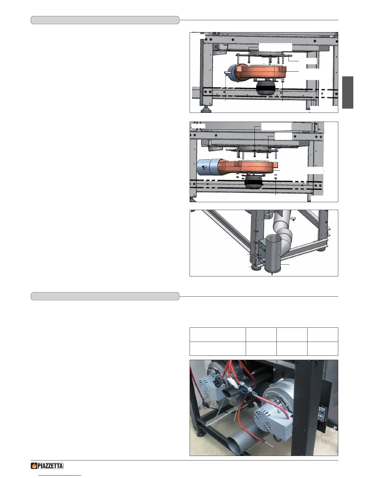
Rotating the position of the ue outlet
If it is necessary to move the position of the outlet to the left-hand side,
remove the fan as follows:
- loosen the screw that secures the smoke sensor to its niche; (Fig. 28);
- support the fan with one hand and remove the three nuts with washers
that secure it to the structure; (Fig. 28);
- support the ange and remove the three screws M6x30 xing it to the
bottom of the stove; (Fig. 28);
- turn the ange to the left until its holes are aligned with those in the
new position under the stove (an arrow on the ange indicates the
direction of ue outlet).
a During these procedures of disassembly and assembly, take
care not to damage the gasket of the ange and the fan.
- Replace the screws M6x30; (Fig. 29);
- insert the fan onto the three pins of the ange and x it with the nuts
and washers;
- replace the smoke sensor in its niche and x it.
a The sensor cable must not touch hot parts, so be sure it is
suitably positioned.
- Now install the union tee (optional) on the right or left, securing it with
the screw, washer and nut provided together with the union. (Fig. 30)
The standard product comes with the electronic boards tted on the right side of the stove. If necessary the electronic board support can, however,
be placed on the left side of the stove.
a In the case of installation of the product with side ue gas
outlet, the electronic board support must necessarily be
placed on the side opposite the ue gas outlet connection.
To move the electronic board support, proceed as follows:
a The power cable must be disconnected from the stove before
carrying out any of the steps described below.
- Loosen the fastening screw and disconnect the smoke sensor (1)
from the relative housing to be found in the ue gas outlet pipe.
- Disconnect the low-pressure tube from the outlet connector (2) to be
found in the rear of the stove.
DT2011823-00
5.2 SIdE FLUE OUTLET
DT2011788-00
5.3 POSITION OF ELECTRONIC bOARdS
SENSOR NICHE
COMBUSTION
GAS FAN
NUT AND WASHER
FLANGE
SCREW M6x30
SCREW M6x30
FLANGE
COMBUSTION GAS FAN
NUT AND WASHER
WASHER
SCREW
SIDE OUTLET
Fig. 28
Fig. 31
Fig. 29
Fig. 30
FLUE GAS OUTLET
CONNECTION
REAR RIGHT LEFT
ELECTRONIC BOARD
SUPPORT POSITION
Right or left
side
Left side Right side
1
2
H072047UK0 / DT2001513 – 04
19