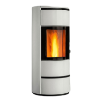
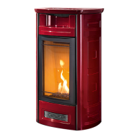
The standard MP 973 stove comes with hopper opening on the right
side. (Fig. 37)
The opening may, however, be moved to the left side, proceeding as
follows:
- remove the screws fastening the top element of the cover;
- remove the screws fastening the hopper closing plate on the left side;
- invert the positions of the top element of the cover and the hopper
closing plate;
- now secure both elements using the previously removed screws.
a In the case where the appliance is installed with side smoke
extractors, the tank opening must be positioned on the side
opposite the smoke extractor connector.
• Thanks to Piazzetta technology and R&D, this pellet stove offers the
advantages of the “Multifuoco system”, a system EXCLUSIVE to and
PATENTED by Gruppo Piazzetta S.p.A., a true innovation in the eld of
pellet stoves.
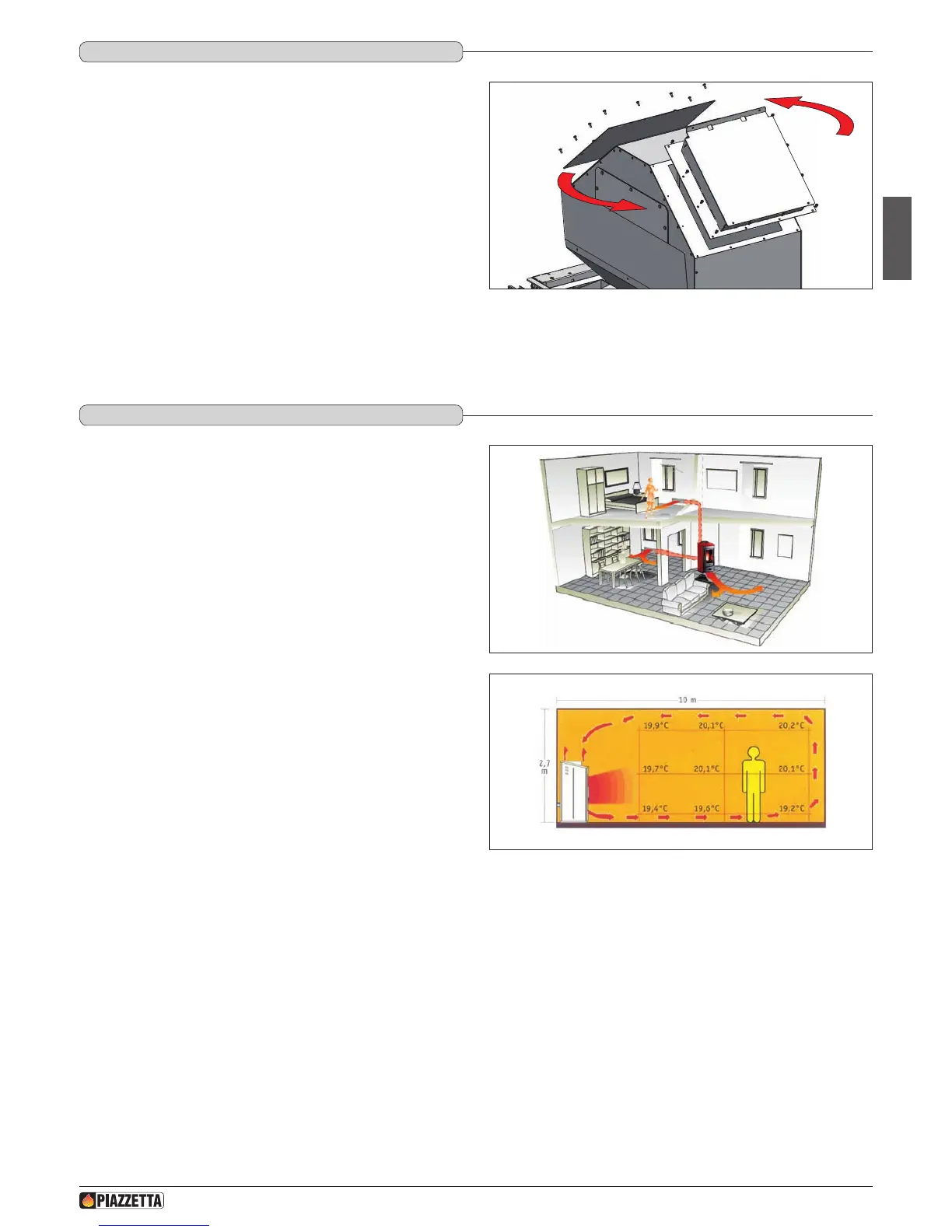
• The “Multifuoco system” revolutionises all methods of heat circulation
currently in use in pellet stoves: the heat produced by the rebox is
not only circulated from the lower part of the stove into the room, but
hot air can also be ducted via Ø 75 mm hoses to adjoining rooms (Fig.
38).
This exclusive oor-standing heat distribution system offers notable
advantages: even spread of temperatures (Fig. 39).
The hot air produced is propelled by two fans and distributed via the
grille at the back of the stove.
Instructions for ducting hot air
• The ventilation kit which expels heat into the atmosphere is equipped
with two Y shaped elements (one per motor) which allow the air ow
to be doubled up, directing it via a exible pipe to the back of the stove
from where it can be directed into other environments.
• The following are some examples of installation of the stove and
examples of warm air ducting systems for heating. These examples
are merely indicative, performance is optimal with 7.5 cm diameter
pipes coated as described in the subsection “Wall and ceiling
ducting systems” and with a maximum total length of pipe of 16
meters.
This length is given by the sum of the individual lengths of pipes for
each fan, plus the elbows and Y elements and is subject to checks of
the dimensions and the insulation classication of the environment to
be heated.
a Every bend and/or Y connector is comparable to 1 metre of
straight ducting.
DT2011768-01
5.4 hOPPER OPENING
DT2011770-01
5.5 MULTIFUOCO SySTEM
Fig. 37
Fig. 38
Fig. 39
H072047UK0 / DT2001513 – 04
21