Power cable (7)
• The stove/rebox comes with a power cable which must be connected to a
230v/50Hz mains socket. Connection to the socket in the right side of the
stove/rebox is shown in g. 54.
• The power rating is indicated in the paragraph “TECHNICAL DATA”.
a The appliance must be connected to an efcient earthing/
grounding system.
a Ensure that in its normal position the power cable does not come
into contact with any heated parts.
a Ensure that the electrical plug is accessible also after installation
of the stove.
External socket for connection to the room sensor (5)
• When installing the stove/rebox, it is necessary to connect the room
sensor (provided) to the correct jack (Fig. 52). The sensor can be positioned
as shown in g. 53, otherwise remove the band and uncoil the lead and
then place the sensor in a spot where a more accurate room temperature
reading can be obtained.
Pipe tap (3)
• The appliance has an external socket for measuring the pressure (vacuum)
of the ue gas outlet pipe. This control and verication should be carried out
by authorised personnel at the time of installation or during maintenance.
Connection to the DB9 serial socket (7)
• The appliance has a DB9 serial socket, which is used to check appliance
operation. Controls should be carried out by authorised personnel at the
time of installation or during maintenance.
• The optional GPRS kit, if ordered, may be connected to the DB9 serial
socket.
DT2011810-01
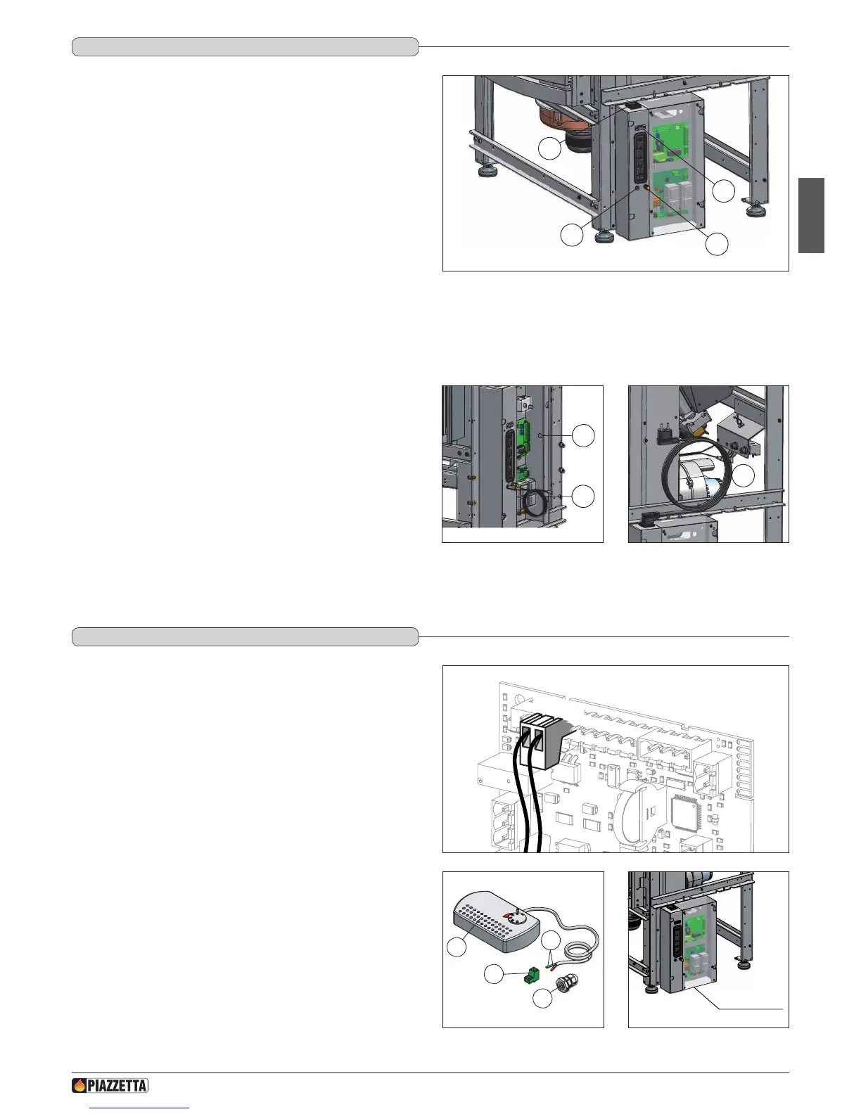
5.7 ELECTRICAL CONNECTIONS ANd CONTROLS
1
2
3
7
Fig. 52
1 External jack for connection of room sensor.
2 Socket for power lead.
3 Pipe tap.
4 Cable gland PG7 for connection of external thermostat.
5 Room sensor connection.
6 Power lead connection
7 DB9 serial socket
6
4
5
Fig. 53 Fig. 54
The appliance is designed to be connected to an external room thermostat
with a normally open contact (not supplied by the manufacturer).
The thermostat is connected using a cable 2x0.5 mm
2
secured with cable
gland PG7 to be inserted in the hole in the electronic board support (Fig. 53).
This operation should be carried out by authorised personnel.
To install, proceed as follows:
- cut off the electricity supply;
- remove the electronic board protective panel (Fig. 57);
- remove the knockout to be found in the electronic board support (position
4 – gure 56);
- insert the thermostat cable in the cable gland PG7 and then insert the gland
into the hole obtained from removing the knockout in the electronic board
support (Fig. 53);
- connect the terminal of the room thermostat cable to the 2-pin terminal of
the electronic board (Fig. 55);
- replace the electronic board protective panel.
a Do not connect any live element to the terminal TERM.
DT2010338-01
5.8 INSTALLING ThE ExTERNAL ThERMOSTAT
TERM
Fig. 55
Electronic board
protective panel
1
2
3
4
1 Thermostat
2 Electronic board 2-pin terminal
3 Cable gland PG 7
4 Thermostat cable terminal
Fig. 56 Fig. 57
H072047UK0 / DT2001513 – 04
25