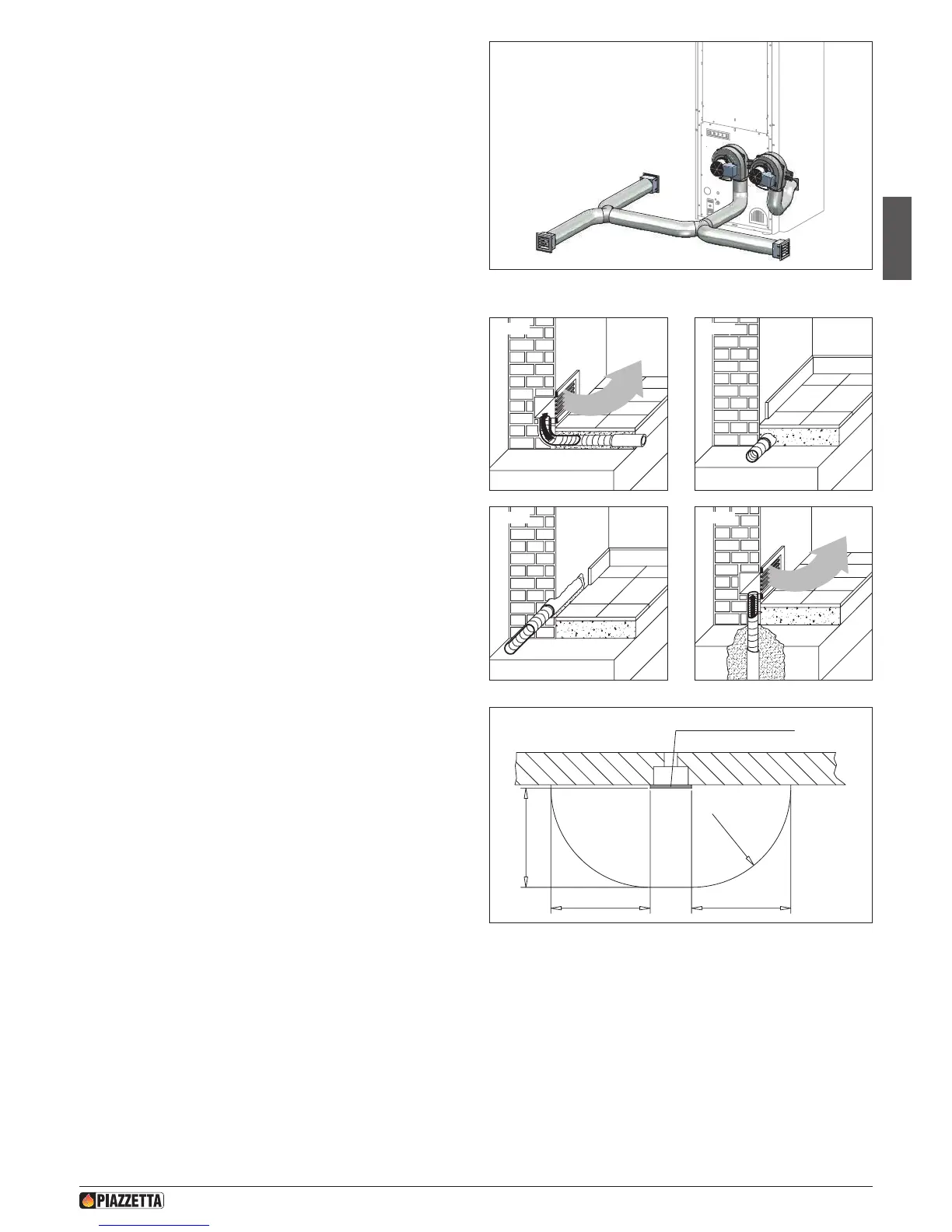
Solution 4 - Fig. 43:
Extending the previous solution with the appliance installed in the room
to be heated and heat directed to the front and rear of the appliance
with doubling-up using a second Y element at the rear as shown.
a For the example shown in Figure 43, you can install an outlet
with closure for the shortest section allowing for some of the
air to be released, without ever closing completely to prevent
overheating.
Wall and oor ducting - Fig. 44 / 47
For efcient ducted heat distribution:
- Lag the hose with a 2 cm thick insulation (e.g. mineral bre, ceramic
bre, rock bre) to limit heat loss and to guarantee a sufciently warm
air temperature.
- The insulation must have a specic weight equal to or more than
50 kg/m³ with working temperature limit of at least 250°C. Thermal
conductivity λ (100°C) ≤ 0,050 W/mK.
- Material with code “AGI Q132” or “DIN 18895” is allowed for thermal
insulation.
a If the insulating material is not enclosed under the oor or
within the walls, it must be xed to the surface with suitable
fastenings at intervals of 30 cm.
A few examples of how the hose can be installed in walls or oors are
given to the side.
Hot air outlet vent radiation area (mm) - Fig. 48
A safety area must be ensured around the hot air outlet vent within
which there must be no ammable objects (furniture, carpets, curtains,
etc.) or heat sensitive materials (wood, plastic, etc.).
The diagram to the side shows the measurements for this safety area,
which includes 600 mm from the upper edge of the vent.
a If the oor is ammable, the hot air outlet vents must be
located at least 200 mm from the oor.
Fig. 43
R600
600
600600
HOT AIR OUTLET VENT
Fig. 44 Fig. 45
Fig. 46 Fig. 47
Fig. 48
H072047UK0 / DT2001513 – 04
23