7 General
Installation manual PMCprimo Drive2
Page 25
7.12 Regen circuit
During braking with the aid of the motor, energy is fed back to the PMCprimo Drive2. This energy is
converted into heat in the regen resistor. The regen circuit (thresholds) are adjusted to the supply
voltage with the help of the setup software PDRIVE.
Our applications department can help you with the calculation of the regen power which is required.
A description of the interface can be found on page 50 .
Internal regen resistor: PMCprimo Drive2 sz. 01/03 66 Ohm
PMCprimo Drive2 sz. 06-20 33 Ohm
External regen resistor: PMCprimo Drive2 sz. 01-20 33 Ohm
Functional description:
1. Individual amplifiers, not coupled through the DC-link (DC+, DC-)
The circuit starts to respond at a DC-link voltage of 400V, 720V or 840V (depending on the supply
voltage). If the energy which is fed back from the motor, as an average over time or as a peak
value, is higher than the preset regen power, then the PMCprimo Drive2 will output the status
“regen power exceeded” and the regen circuit will be switched off. At the next internal check of the
DC-link voltage (after a few ms) an overvoltage will be detected and the PMCprimo Drive2 will be
switched off with the error message “Overvoltage” (⇒ page 82).
BTB/RTO contact (terminal X3, Pin2+3) will be opened at the same time (⇒page 64)
2. Several servo amplifiers coupled through the DC-link circuit (DC+, DC-)
Thanks to the built-in regen circuit with its patented w-characteristic, several amplifiers (even with
different current ratings) can be operated off a common DC-link, if they have a common supply
voltage. This is achieved by an automatic adjustment of the regen thresholds (which vary, because
of tolerances). The regen energy is distributed equally among all the amplifiers. The combined
power of all the amplifiers is always available, as continuous or peak power. The switch-off takes
place as described under 1. (above) for the PMCprimo Drive2 with the lowest switch-off threshold
(resulting from tolerances). The RTO (BTB) contact of this amplifier (terminals X3, Pin2+3) will be
opened at the same time (⇒ S. 64).
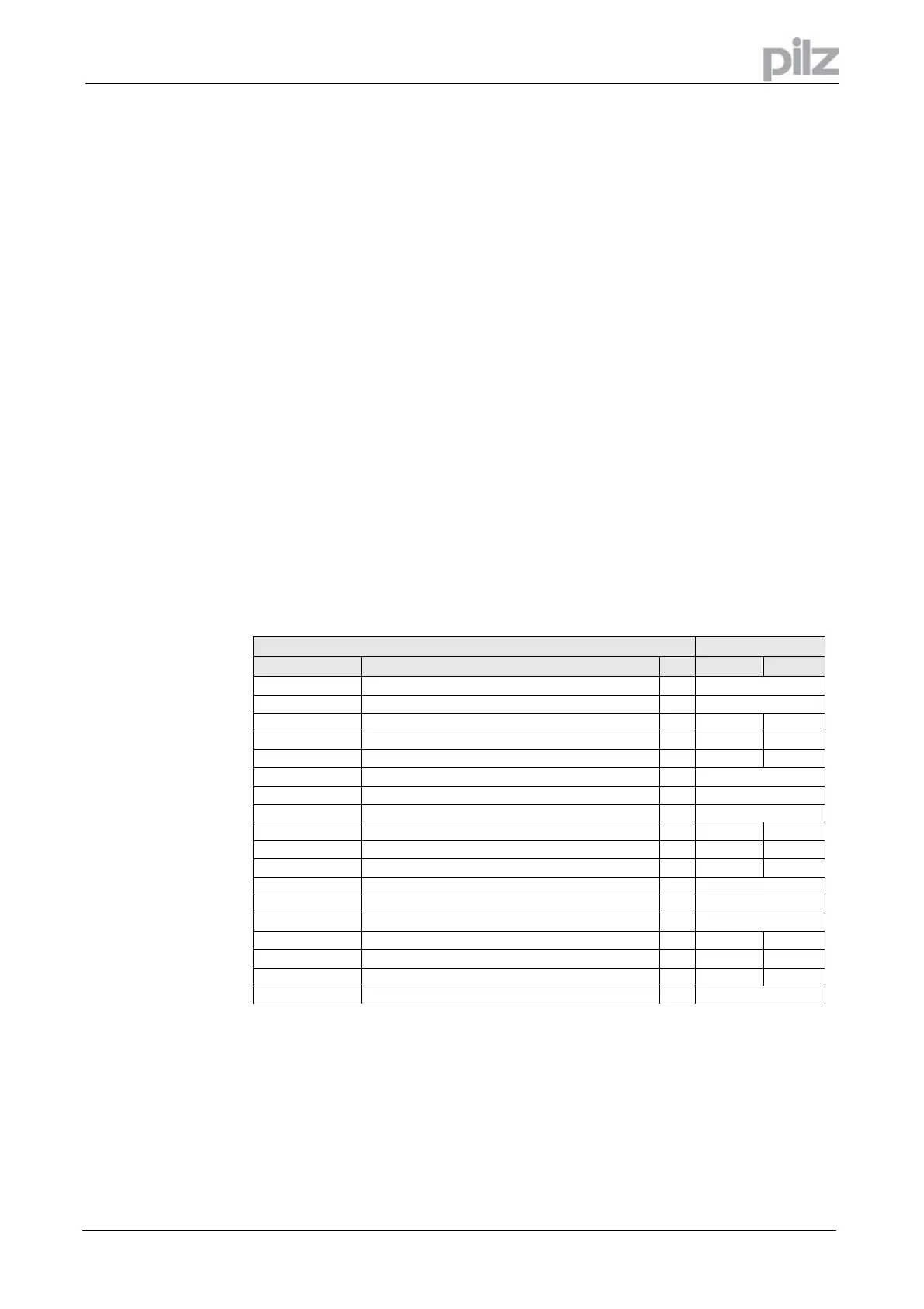
Regen circuit: technical data
PMCprimo Drive2
Supply voltage
Rated data
DIM 01 - 03 06 - 20
3 x 230 V Upper switch-on level of regen circuit V 400 – 430
Switch-off level of regen circuit V 380 – 410
Continuous power of regen circuit (RBint) W 80 200
Continuous power of regen circuit (RBext) max. kW 0,25 0,75
Pulse power, internal (RBint max. 1s) kW 2,5 5
Pulse power, external (RBext max. 1s) kW 5
3 x 400 V Upper switch-on level of regen circuit V 720 – 750
Switch-off level of regen circuit V 680 – 710
Continuous power of regen circuit (RBint) W 80 200
Continuous power of regen circuit (RBext) max. kW 0,4 1,2
Pulse power, internal (RBint max. 1s) kW 8 16
Pulse power, external (RBext max. 1s) kW 16
3 x 480 V Upper switch-on level of regen circuit V 840 – 870
Switch-off level of regen circuit V 800 – 830
Continuous power of regen circuit (RBint) W 80 200
Continuous power of regen circuit (RBext) max. kW 0,5 1,5
Pulse power, internal (RBint max. 1s) kW 10,5 21
Pulse power, external (RBext max. 1s) kW 21
Artisan Technology Group - Quality Instrumentation ... Guaranteed | (888) 88-SOURCE | www.artisantg.com
 Loading...