9 Interfaces
Installation manual PMCprimo Drive2
Page 55
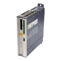
9.5.3 SSI emulation (X5)
The SSI interface (synchronous serial absolute-encoder emulation) is part of the delivered package,
too.
In the PMCprimo Drive2, the position of the motor shaft is calculated from the cyclic-absolute
signals of the resolver or HIPERFACE encoder. A position output is generated from this
information, compatible with the data format of normal commercial SSI absolute encoders. This
synchronous, serial, cyclic-absolute 12-bit (singleturn) or 24-bit (multiturn) information is output on
the SUB-D-Connector X5.
The signal sequence can be output in Gray code (standard) or in binary code (Parameter „SSI-
Code“, window „Encoder“ in PDRIVE ).
A serial signal is read out from the control, with a synchronous clock frequency of max. 1.5 MHz.
The servo amplifier can be adjusted to the clock frequency of your SSI-evaluation with the SSI-
CLOCK parameter (200 kHz or 1.5MHz and inverted).
The drivers are supplied from an internal supply voltage.
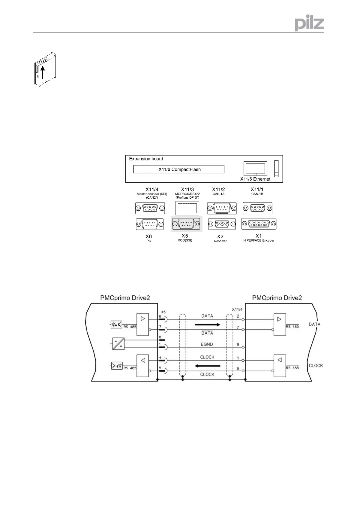
9.5.4 Application example
The count direction for the SSI interface is upwards when the motor shaft is rotating clockwise
(looking at the shaft end).
Artisan Technology Group - Quality Instrumentation ... Guaranteed | (888) 88-SOURCE | www.artisantg.com
 Loading...