PIPER AIRCRAFT
PA-44-180/180T
AIRPLANE MAINTENANCE MANUAL
8. Replace the four screws. Dress wires away from standoffs to avoid pinching wires between standoffs
and the battery pack.
9. Install unit into mounting tray:
a. Connect molex and coax cables to ELT unit.
b. Install mounting tray cap and secure to front of mounting tray with the two screws.
11. Install positive cable to battery.
10. Test transmitter.
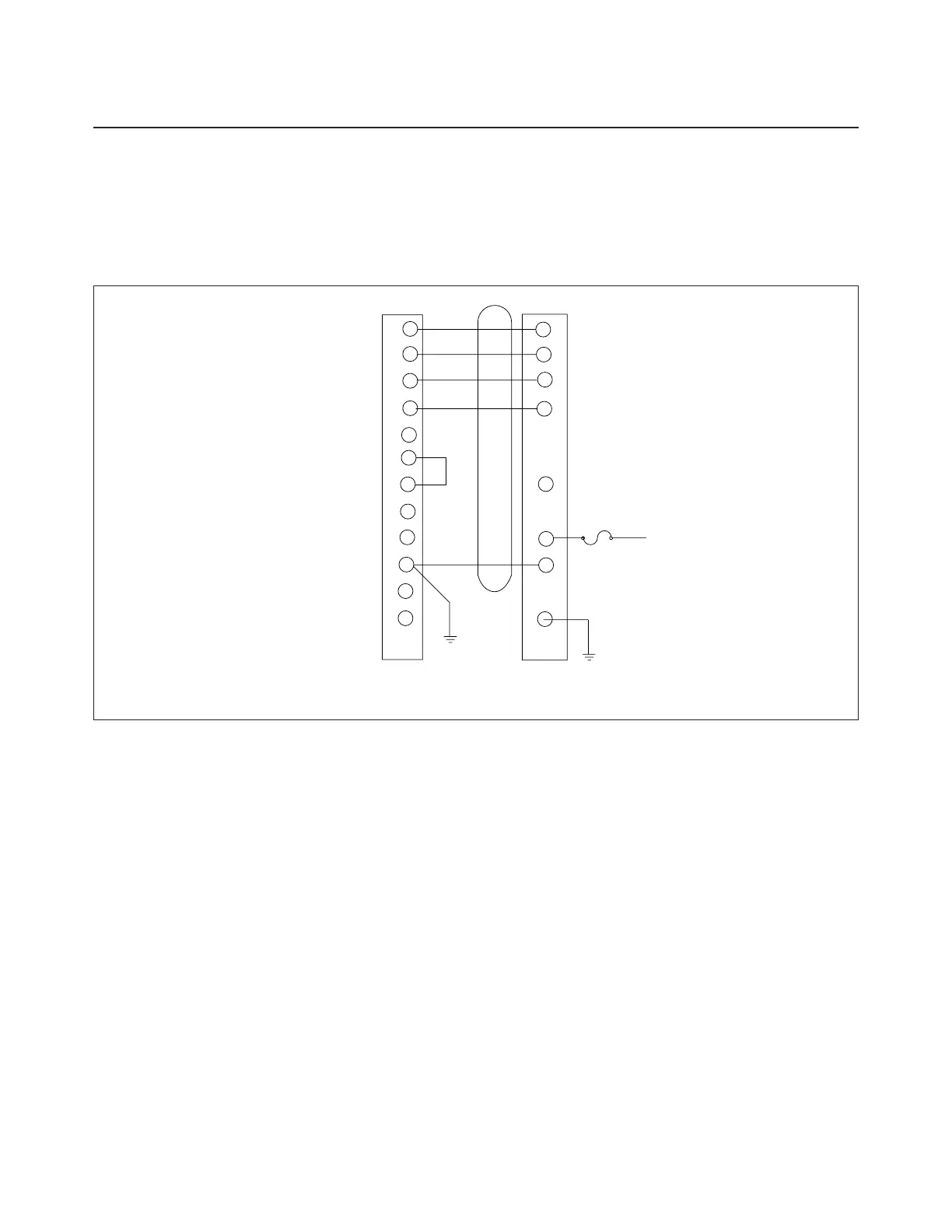
Figure 23-8. Artex E. L. T. 110 Wiring Schematic
TESTING THE ARTEX ELT 110 EMERGENCY LOCATOR TRANSMITTER
— NOTE —
Consult FAA Advisory Circular AC 20-81 for detailed testing
information and precautions
1. Conduct test only during the first five minutes after any hour.
2. If operational test must be made at any time other than the first five minutes after the hour, notify the
nearest FAA traffic Control Tower or Flight Service Station prior to the test.
3. Test should be no longer than three audio sweeps.
4. Tune airplane communications receiver to 121.5 mHz. Check that aircraft battery and radio master
switches are ON.
5. Position ELT cockpit switch to ON. The ELT should immediately begin signaling and the panel light
should immediately come ON. Although the light may illuminate after a few seconds, failure of the
light to immediately come ON indicates trouble with the g-switch circuit, pins 5 and 8 on tray connector,
and that the unit is not working properly. Repairs should be done only by a licensed aviation radio
repair shop.
23-16-02
Page 23-08
Added: June 20, 1995
1I9
 Loading...