CYLINDER HEAD TEMPERATURE GAUGE CALIBRATION (PA-44-180 S/N 44-95001 and up)
A calibration chart has been included for use in verifing that the suspected faulty gauge is within tolerance.
Actual recalibration of the gauge must be performed by the manufacturer or an approved instrument repair
facility.
1. With the instrument installed in the aircraft, the aircrafts’ power connected (14 VDC) and the ground
connected.
2. Remove the connection to the terminal marked SEND and connect a specified amount of resistance as
indicated on the chart, by use of a fixed resistor or a test unit capable of simulating the resistance indicated
on the chart (Power Resistor Decade Box).
3. If the gauge does not meet the tolerances set forth in the chart, it must be replaced or recalibrated.
4. Reinstallation should be the reverse of the procedure used to disconnect it.
— Note —
To facilitate installation, mark or label all wires prior to removal.
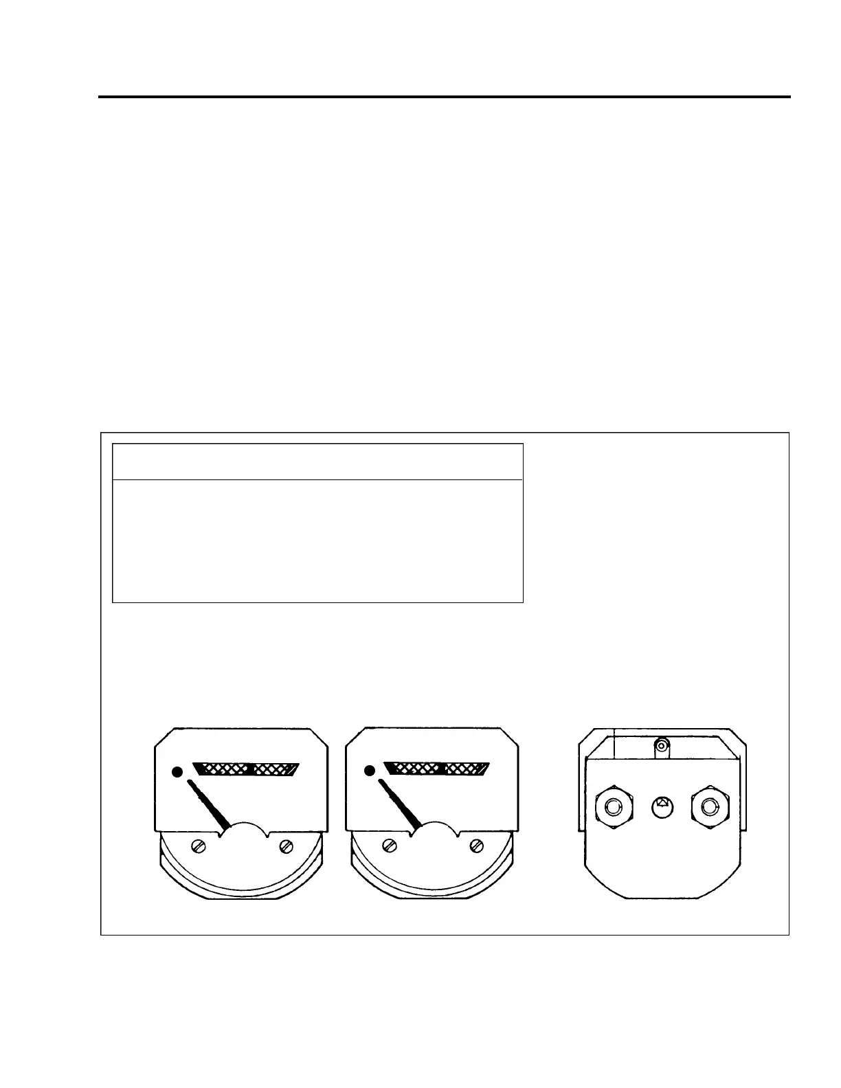
Figure 77-3. Cylinder Head Temperature Calibration (PA-44-180 S/N 44-95001 and up)
CALIBRATION CHART
GRADUATION OHMS DEGREES TOLERANCE*
DOT MECH ZERO -40° ± 1/2
200° F 745 -30° ± 1
350° F 110 +5° ± 1
500° F 34 +28° + 1, - 0
* NOTE:
TOLERANCES IS IN POINTER WIDTHS
USE 14 VDC
USE WITH SW338 OR ROCHESTER
GAUGE 3080-14 SENDER (“Q’ CURVE)
SEND IGN
GND 14 VDC
200 350 500
R. CYL. HEAD TEMP. °F
200 350 500
L. CYL. HEAD TEMP. °F
PA - 4 4 - 1 8 0 / 1 8 0 T
AIRPLANE MAINTENANCE MANUAL
7 7 - 2 1 - 0 2
Page 77-10
Revised: May 15, 1989
3H12
PIPER AIRCRAFT
 Loading...