Chapter H - PARTS REPLACEMENT & REPAIR
Planmeca Proline XC X-ray unit H-9
REPLACING THE SOFTWARE
Technical Manual
5 REPLACING THE SOFTWARE
5.1 Keyboard processor PCB software
Remove the lower shelf cover as described in section 1.5 “Lower shelf cover” on page H-4.
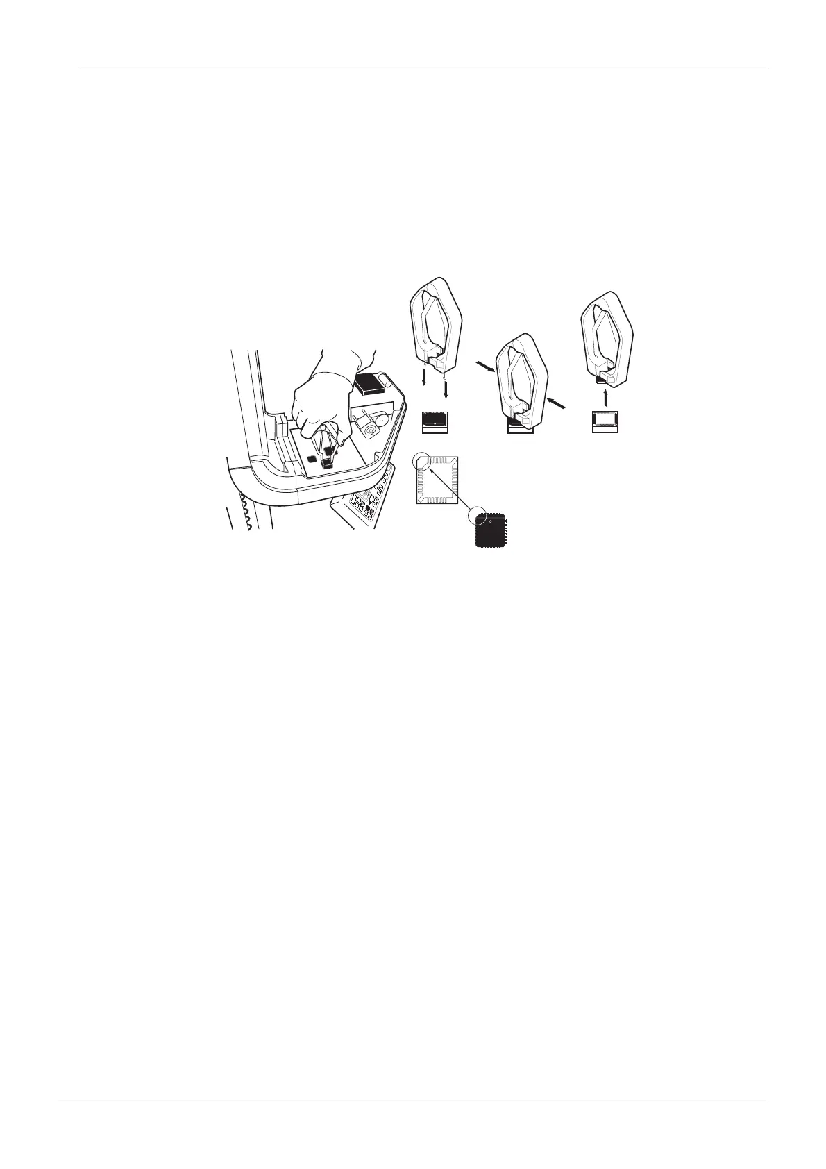
Remove the software chip from its socket with the special tool as illustrated on Fig. 6 below.
Figure 6
Carefully place the new software chip into the socket.
NOTE The orientation of the software chip is critical. Never try to force the chip into the
socket.
Attach the lower shelf cover to its position.
5.2 Generator processor PCB software
Remove the tube head inner cover and the rotating arm cover as described in sections 1.3
“Tube head covers” on page H-3 and 1.4 “Rotating arm cover” on page H-3.
Detach all the cables from the generator processor PCB.
Keyb_pros.eps






 To Next Page