Chapter I - FUNCTIONAL DESCRIPTION
Planmeca Proline XC X-ray unit I-7
MECHANICAL CONSTRUCTION AND OPERATION
Technical Manual
1.6 Collimator/primary collimator mechanism, Planmeca
Proline XC Pan/Ceph X-ray unit
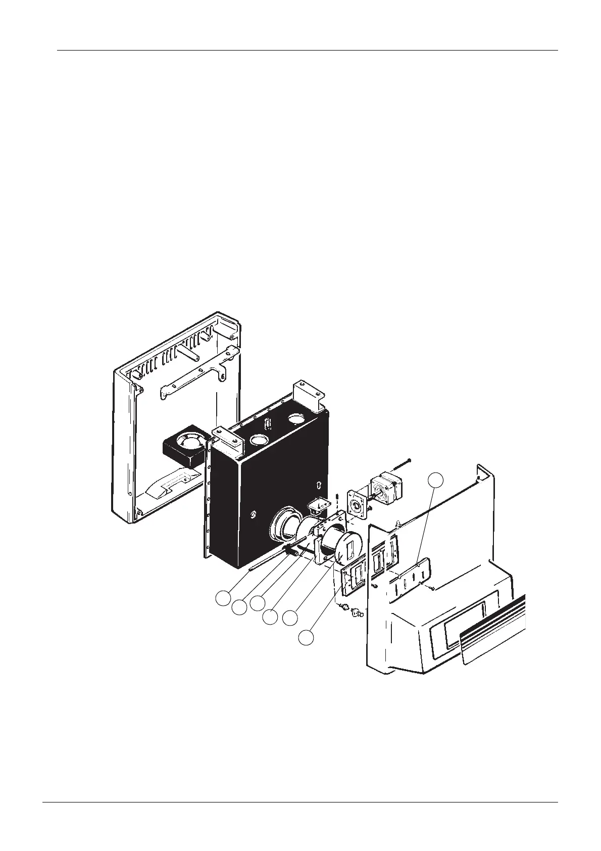
The collimator tube (Fig. 6, 1) is attached with screws to the radiation window frame. Under a
nut there is an inner primary collimator sheet which consists of an aluminium filter plate and
lead plates with holes. The lead plate reduces the radiation beam for the actual primary colli-
mator. The aluminium plate filters the harmful soft radiation. In the outer part of the collimator
tube there is a second inner primary collimator (Fig. 6, 2) which reduces secondary radiation
scattering from the inner parts of the collimator tube.
Part (Fig. 6, 3) is the frame of the primary collimator mechanism. The primary collimator (Fig.
6, 4) is attached to a collimator carriage (Fig. 6, 5) which is attached with bearings to the
frame. The stepper motor draws the collimator carriage through a screw (Fig. 6, 6) and a nut
(Fig. 6, 7). The drive nut has a plate which together with an optic sensor (Fig. 6, 2) composes
the place reference for the primary collimator.
The microprocessor controls the stepper motor. Motor commandment is described in section
“Motors” on page I-14.
The function of the PCB 105-10-08 is described in section “Circuit boards” on page I-12.
Figure 6
1
4
3
2
6
5
7