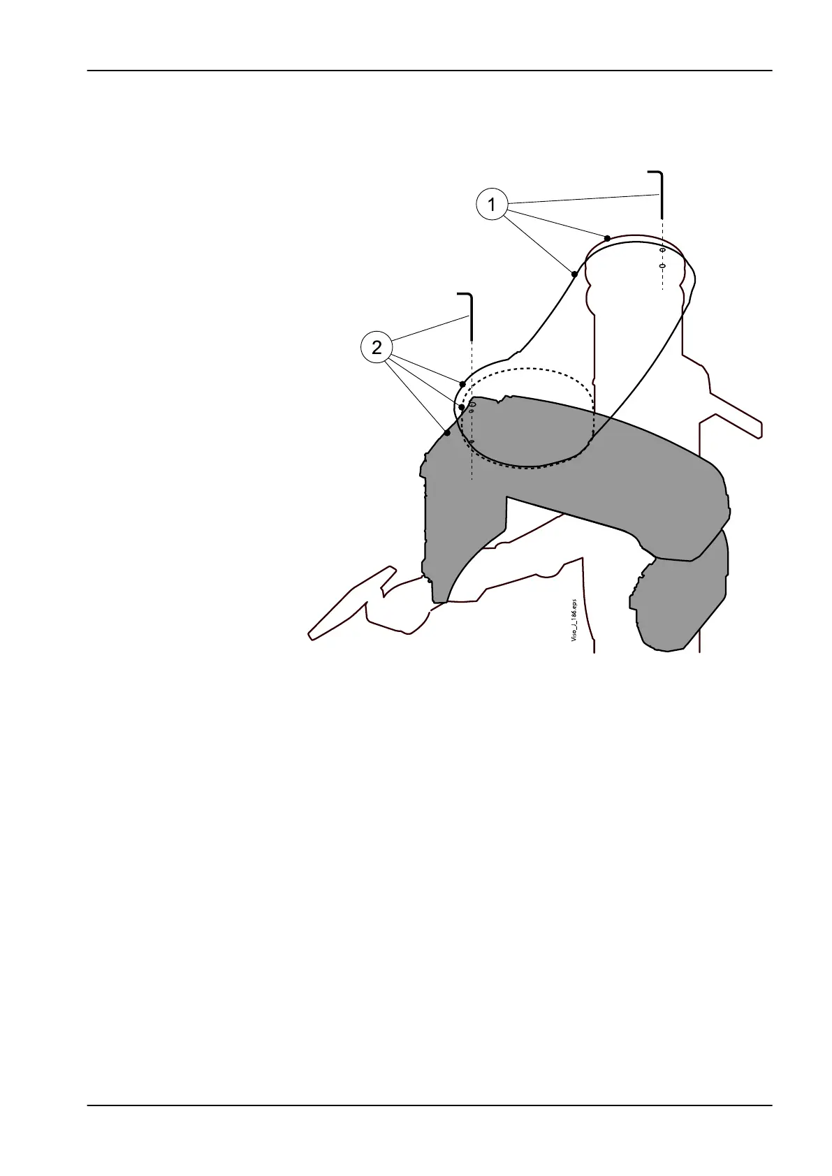
8. Move the C-arm and middle arm to the positions shown on the figure
below. Slide the alignment pin through the hole in the upper joint so that
it goes into the positioning hole in the C-arm (2).
9. Lock the stepper motors by touching the blue Release motors button.
10. After locking the motors remove the alignment pins and calibrate the
position sensors by touching the Automatic position sensor calibration
button.
11. The position sensors are now calibrated.
Check the values and arrows on the display. They should all be green.
If the green arrow of the column joint position sensor cannot be reached
with the pin in the position, the sensor need to be adjusted. Refer to
section "Adjusting column joint position sensor" on page 109.
12. Exit the calibration mode by touching the green check mark button.
5.10.3 Adjusting column joint position sensor
1. Loosen the attachment screw of column joint angle sensor coupling with
1.5 mm Allen key (1).
5 Adjustments and calibrations
Technical manual Planmeca Viso 109



 To Next Page