on local regulations. Check that this buzzer also comes on for the length of
the exposure if it is enabled.
Exposure switch
Confirm that the exposure switch requires continuous activation to maintain
the exposure. Releasing the exposure switch during the radiation should
stop the exposure and produce an error message. Make a visual check and
check for possible wear or damage of the exposure switch spiral. Replace if
necessary.
Exposure indicators
Confirm that the exposure indicator lights turn on in the control panel and in
the exposure switch for the length of the exposure. Additionally, check also
the (optional) external exposure indicator, if the unit is equipped with such.
4.2 Electrical safety measurements
All the measurements shall be performed using an IEC62353-compliant
measurement device. The unit shall be separated from the supply main (live,
neutral and protective earth) during the measurements.
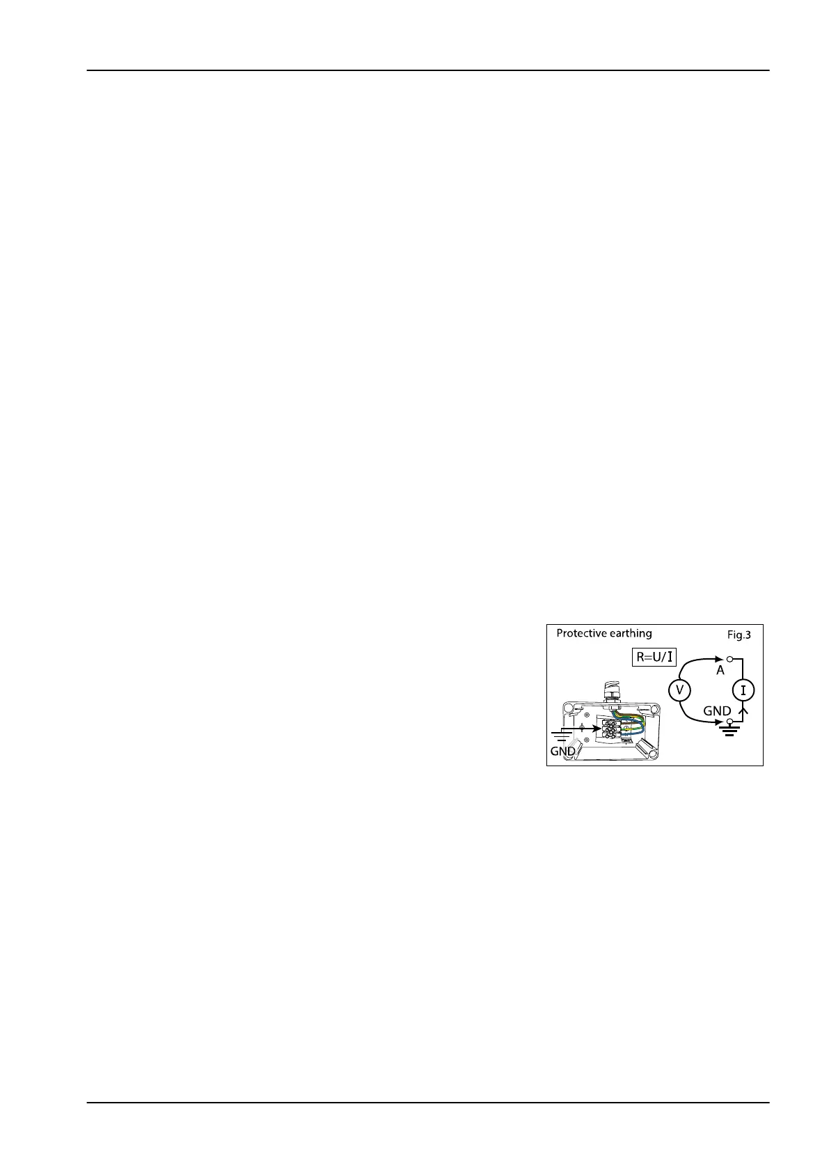
Protective earthing
For equipment with a non detachable power supply cord the impedance
between the protective contact in the mains and any accessible metal part,
which is protectively earthed, shall not exceed 300 mΩ.
Measurements shall be peformed using a measuring device able to deliver a
current of at least 200 mA into 500 mΩ. The open circuit voltage shall not
exeed 24 V.
Measure between the main ground point and grounding point in C-arm and
input module.
4 Annual maintenance
Technical manual Planmeca Viso 49



 To Next Page