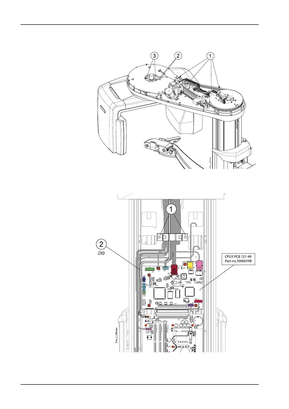
4. Cut the cable ties (1). Unscrew the position sensor assembly attachment
screws (2 and 3).
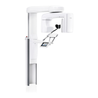
5. Unscrew two cable holder attachment screws (1) and remove the holder.
Disconnect the position sensor cable from the CPU3 PCB (2).
6. Route the position sensor cable out from the column and remove the
position sensor from its position.
7. Attach the new position sensor in reverse order.
6 Parts replacement
144 Planmeca Viso Technical manual



 To Next Page