Pleiger Elektronik
GmbH & Co. KG
Page: 14 Manual for 362MC Edition: 6/2007 Subject to modifications
Measuring sensor Measuring Parameters Comment
for example: range
Scale-FScale-F
Scale-FScale-F
Scale-F
Scale-0Scale-0
Scale-0Scale-0
Scale-0
DimDim
DimDim
Dim
SetpSetp
SetpSetp
Setp
PT100 0 to 500°C 500,0 0,0 °C 0 - 500,0 °C The required hardware
Pressure sensor -1 to 5 bar 6,0 -1,0 B -1,0 - 5,0 bar configuration for the
Displacement sensor 0 to 300 mm 300,0 0,0 mm 0 - 300,0 mm installed 362MC is to be
Rotation angle sensor 0 to 100% 100,0 0,0 % 0 - 100,0 % observed.
If no other error: Alarm relay energised = actual value within alarm limits;
Alarm relay not energised = limit value alarm;
see also Monitoring functions and error messages (6).
""
""
"
W
t
Tf
Alarm ON
Alarm OFF
Alarm ON
5.3.1 Explanatory note on setpoints
The table for the Setpoint menu shows a permissible range from 0-200°C for setpoints “Setp A” and
“Setp B” of each controller. This range is valid for PT100 inputs in standard configuration. Additional
setpoint ranges can also be set, in each case adapted via the scaling factor to the employed measuring
sensors and the physical variables to be controlled.
These settings are carried out in the Input menu via parameters Scale-F, Scale-0 and Dim.
Several examples of other value ranges are shown in the following table.
See also
Input menu (5.6)
5.3.2 Explanatory note on the switching filter
In order to avoid discontinuous transient conditions and overshoot
during setpoint switching, a switching low pass filter of the 2
nd
order
can be parameterised on the 362MC.
The time for the switching filter is set via the parameter
Tf = T-Lowp.
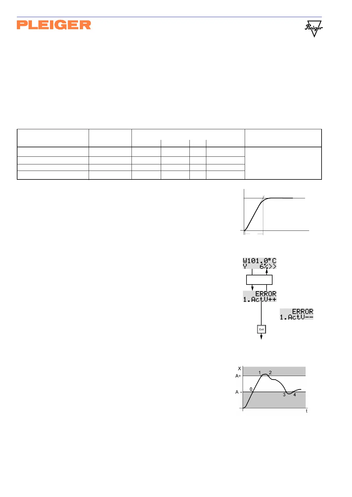
5.3.3 Explanatory note on the limit value alarm
Alarm limits can be parameterised to monitor the actual values and
a permissible system deviation. These impose a lower alarm limit
and an upper alarm limit on the permissible control band. If the
actual value violates a fixed alarm limit for longer than 5s or a
relative alarm limit for longer than 60s, the alarm will be activated.
When an alarm is activated, the alarm relay is de-energised (Alarm ON)
(closed-circuit principle) and the current display is switched to the
error display. This display remains active until the alarm is
acknowledged via the Exit button. The alarm relay is energised
again (Alarm OFF) when the actual values is insite the control band.
For example:
Point 0: The 1
st
actual value attains the control band for the 1
st
time.
Alarm OFF; the alarm display function is started.
Point 1: The upper alarm limit is violated! The alarm is activated
(Alarm ON) and the error indication ActV++ is displayed.
Point 2: The upper alarm range is left again.
Alarm OFF; the alarm relay is energised.
Point 3: The lower alarm limit is violated. The alarm is activated
(Alarm ON) and the error indication ActV— is displayed.
Point 4: The lower alarm range is left again.
Alarm OFF; the alarm relay is energised.
Operational
display
Error
display
or
Alarm
acknowledge
alternate
each second
only
Operational display
Error display