Pleiger Elektronik
GmbH & Co. KG
Page: 20 Manual for 362MC Edition: 6/2007 Subject to modifications
Ys
xd
Tz
Ts
Ts
Tz
Zo
Zo
3PntPW
Ys
xd
Hy
Zo
Hy
Zo
3Point
Ys
xd
Hy
Zo
2Point
Ys
xd
Tz
Ts
Zo
2PntPW
Y
t
Kr
Tn
PI-Step-Structure
CtrlTypCtrlTyp
CtrlTypCtrlTyp
CtrlTyp
2PntPW2PntPW
2PntPW2PntPW
2PntPW
2Point2Point
2Point2Point
2Point
Step Step
Step Step
Step
Cont Cont
Cont Cont
Cont
CscStepCscStep
CscStepCscStep
CscStep
when controller
or or prim. contrl. sec. contrl. of type
3PntPW3PntPW
3PntPW3PntPW
3PntPW
3Point3Point
3Point3Point
3Point (Cont) (
1
) (Step) (
2
)
Para-Para-
Para-Para-
Para-
T driveT drive
T driveT drive
T drive
T driveT drive
T driveT drive
T drive
these parameters
meter meter
meter meter
meter
Ts min Ts min
Ts min Ts min
Ts min
Ts min Ts min
Ts min Ts min
Ts min
Ts min Ts min
Ts min Ts min
Ts min are to be defined
T cyclT cycl
T cyclT cycl
T cycl
Deadbd Deadbd
Deadbd Deadbd
Deadbd
DeadbdDeadbd
DeadbdDeadbd
Deadbd
Deadbd Deadbd
Deadbd Deadbd
Deadbd
DeadbdDeadbd
DeadbdDeadbd
Deadbd
DeadbdDeadbd
DeadbdDeadbd
Deadbd
DeadbdDeadbd
DeadbdDeadbd
Deadbd
Hyst Hyst
Hyst Hyst
Hyst
Ymin Ymin
Ymin Ymin
Ymin
Ymin Ymin
Ymin Ymin
Ymin
Ymin Ymin
Ymin Ymin
Ymin
Ymin Ymin
Ymin Ymin
Ymin
Ymax Ymax
Ymax Ymax
Ymax
Ymax Ymax
Ymax Ymax
Ymax
Ymax Ymax
Ymax Ymax
Ymax
Ymax Ymax
Ymax Ymax
Ymax
Kw Kw
Kw Kw
Kw
Kw Kw
Kw Kw
Kw
Kw Kw
Kw Kw
Kw
Kw Kw
Kw Kw
Kw
Kw Kw
Kw Kw
Kw
Kw Kw
Kw Kw
Kw
StructStruct
StructStruct
Struct
P P
P P
P
PI PI
PI PI
PI
PD PD
PD PD
PD
PIDPID
PIDPID
PID
when structure is
PD2 PD2
PD2 PD2
PD2
PID2PID2
PID2PID2
PID2
Parameter KrParameter Kr
Parameter KrParameter Kr
Parameter Kr
Kr Kr
Kr Kr
Kr
Kr Kr
Kr Kr
Kr
Kr Kr
Kr Kr
Kr
these parameters
Tn Tn
Tn Tn
Tn
Tn Tn
Tn Tn
Tn are to be defined
Tv Tv
Tv Tv
Tv
Tv Tv
Tv Tv
Tv
Vd Vd
Vd Vd
Vd
Vd Vd
Vd Vd
Vd
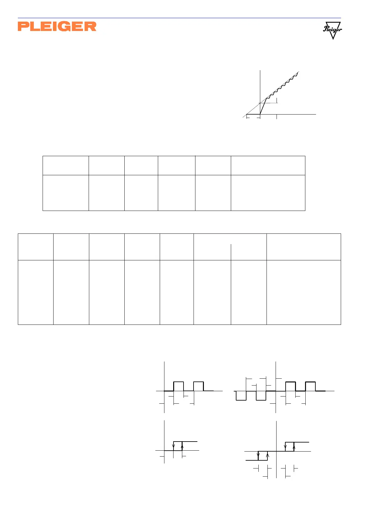
PI step controller (proportional-plus-integral action step controller)
PID step controller (PI step controller with added D component)
In the case of the PI and PID step controller, the value of controller
output Y
can only be generated in conjunction with the I component
of the actuator.
As with the other PI and PID controllers, the P, I and D components are
set via parameters Kr, Tn and TV/Vd. Operating time T drive of the
actuator controls the stepping function of the 3-Point output with feedback.
The display shows only the parameters contained in the following table, corresponding to the structure
defined in “Struct”.
The other control parameters are also displayed only when they are to be defined, checked or altered for
the selected controller type. Parameters which are not relevant are not shown. See table:
5.5.3 Explanatory note on controller output parameters
T drive
Operating time of the actuator for step
controllers which applies from feedback signal
OPEN to CLOSED in continuous drive mode.
Ts min and T cycl
Minimum pulse width Ts and minimum cycle
time Tz for pulse-width modulated outputs, for
purpose of adjustment to actuator and controlled
system.
Deadbd
Deadband Zo as zero drive range for pulse-
width modulated outputs and as threshold value
for OFF command of 2-Point and 3- Point
outputs without feedback. See also Cont
Hyst
Hysteresis Hy for ON commands of 2-Point and
3-Point outputs without feedback.