Pleiger Elektronik
GmbH & Co. KG
Page: 24 Manual for 362MC Edition: 6/2007 Subject to modifications
362MC
Setp W Out+Y Feed Y
Out%Y
ActV X
Dist Z
Tren D
Switching
output
or
Analogue
output
Controller
Actuator Controlled
system
362MC
Setp W Out+Y Feed Y
Out%Y
ActV U
ActV X
Switching
output
or
Analogue
output
Controller
(secondary)
Actuator
Part A Part B
Controller
(primary)
Controlled system
5.8 Display menu
The process variables which are to be shown in the two lines of the LCD display as the
operational display are selected in the Display menu. See also Display (2.1).
Pressing the Prgm button will switch the system to a second display level for as long as the
button remains depressed, thus enabling 4 process variables to be assigned. The operating language
“Lang” can also be selected in this menu. All text displays are shown in the selected language.
The contrast adjustment function for the LCD display can also be selected in this menu.
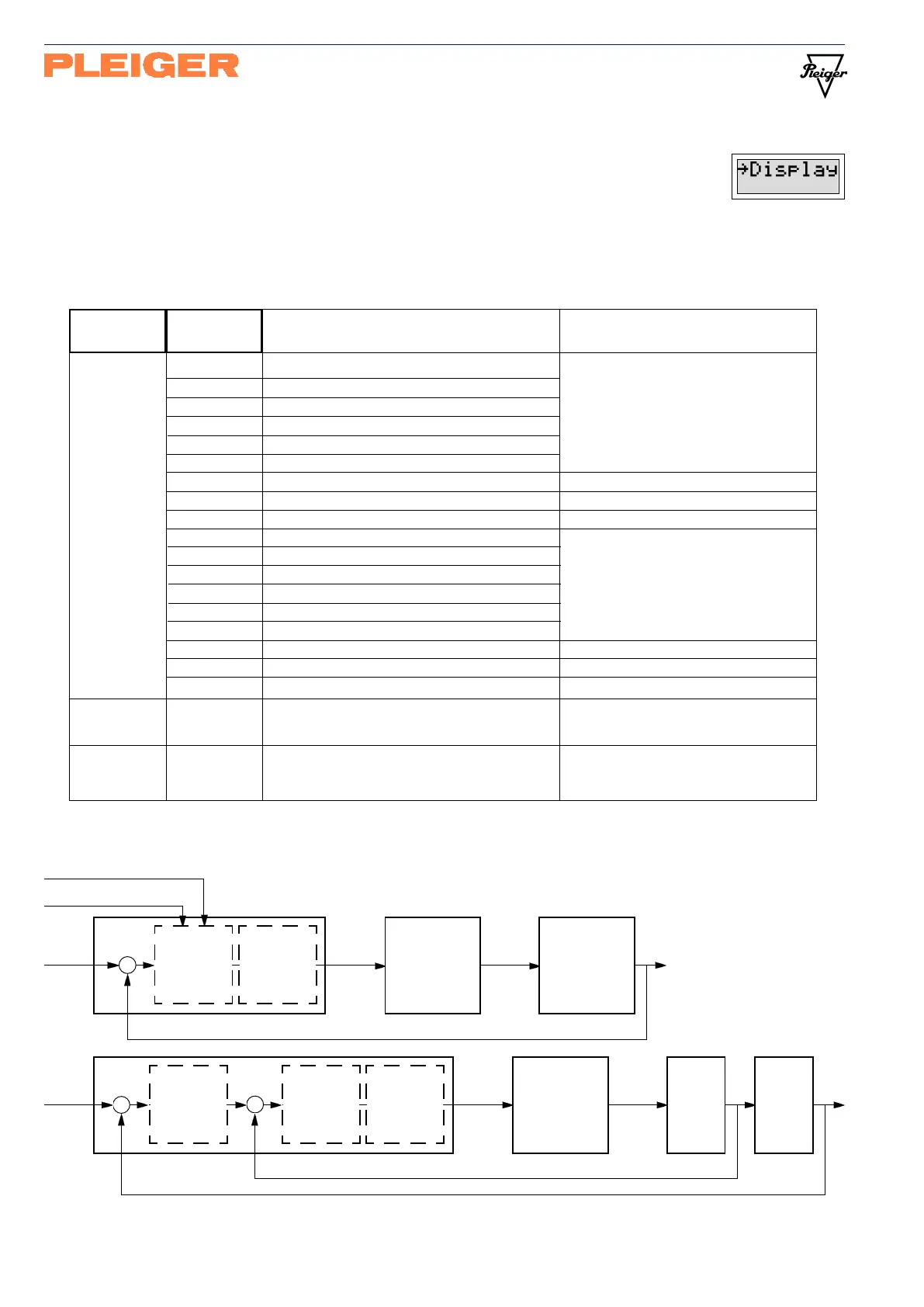
5.8.1 Explanatory note on controller inputs/outputs
The two control diagrams illustrate the significance of the display parameters for
the controller inputs and outputs. The last letter appears on the display as an
upper case letter for controller 1 and as a lower case letter for controller 2.
Parameter Value (min Meaning Comment
general max)
Line 1 Line 1
Line 1 Line 1
Line 1
1Setp W1Setp W
1Setp W1Setp W
1Setp W Setpoint - controller 1
Line 2 Line 2
Line 2 Line 2
Line 2
1Setp V1Setp V
1Setp V1Setp V
1Setp V Setpoint secondary - controller 1 See also Explanatory note on
2nd L1 2nd L1
2nd L1 2nd L1
2nd L1
1ActV X1ActV X
1ActV X1ActV X
1ActV X Actual value - controller 1 controller inputs/outputs
2nd L2 2nd L2
2nd L2 2nd L2
2nd L2
1ActV U1ActV U
1ActV U1ActV U
1ActV U Actual value secondary - controller 1 5.8.1
1Dist Z1Dist Z
1Dist Z1Dist Z
1Dist Z Disturbance input - controller 1
1Tren D1Tren D
1Tren D1Tren D
1Tren D Trend input - controller 1
1Out+Y 1Out+Y
1Out+Y 1Out+Y
1Out+Y Switching control output - controller 1 Display with symbol <<, || or >>
1Feed+Y1Feed+Y
1Feed+Y1Feed+Y
1Feed+Y Position feedback in % - controller 1 Additional to switching output symbols
1Out%Y 1Out%Y
1Out%Y 1Out%Y
1Out%Y Continuous control output in % - controller 1 Display in xx.x%
2Setp w2Setp w
2Setp w2Setp w
2Setp w Setpoint - controller 2
2Setp v2Setp v
2Setp v2Setp v
2Setp v Setpoint secondary - controller 2 See also Explanatory note on
2ActV x2ActV x
2ActV x2ActV x
2ActV x Actual value - controller 2 controller inputs/outputs
2ActV u2ActV u
2ActV u2ActV u
2ActV u Actual value secondary - controller 2 5.8.1
2Dist z2Dist z
2Dist z2Dist z
2Dist z Disturbance input - controller 2
2Tren d2Tren d
2Tren d2Tren d
2Tren d Trend input - controller 2
2Out+y 2Out+y
2Out+y 2Out+y
2Out+y Switching control output - controller 2 Display with symbol <<, || or >>
2Feed+y2Feed+y
2Feed+y2Feed+y
2Feed+y Position feedback in % - controller 2 Additional to switching output symbols
2Out%y 2Out%y
2Out%y 2Out%y
2Out%y Continuous control output in % - controller 2 Display in xx.x%
Lang Lang
Lang Lang
Lang
deutschdeutsch
deutschdeutsch
deutsch Language selection for all
englishenglish
englishenglish
english display texts
LCDcntrLCDcntr
LCDcntrLCDcntr
LCDcntr
1 1
1 1
1 Contrast setting for the
255 255
255 255
255 LCD display