Pleiger Elektronik
GmbH & Co. KG
Edition: 6/2007 Subject to modifications Manual for 362MC Page: 19
CtrlTypCtrlTyp
CtrlTypCtrlTyp
CtrlTyp
2PntPW2PntPW
2PntPW2PntPW
2PntPW
3PntPW3PntPW
3PntPW3PntPW
3PntPW
Step Step
Step Step
Step
Cont Cont
Cont Cont
Cont
CscStepCscStep
CscStepCscStep
CscStep
when controller
or or prim. contrl. sec. contrl. of type
2Point2Point
2Point2Point
2Point
3Point3Point
3Point3Point
3Point (Cont) (
1
) (Step) (
2
)
StructStruct
StructStruct
Struct
P P
P P
P
P P
P P
P
P P
P P
P
P P
P P
P
these structures
PI PI
PI PI
PI
PI PI
PI PI
PI
PI PI
PI PI
PI
PI PI
PI PI
PI
PI PI
PI PI
PI
PI PI
PI PI
PI are possible
PD PD
PD PD
PD
PD PD
PD PD
PD
PD PD
PD PD
PD
PD PD
PD PD
PD
PID PID
PID PID
PID
PID PID
PID PID
PID
PID PID
PID PID
PID
PID PID
PID PID
PID
PID PID
PID PID
PID
PID PID
PID PID
PID
PD2 PD2
PD2 PD2
PD2
PD2 PD2
PD2 PD2
PD2
PD2 PD2
PD2 PD2
PD2
PD2 PD2
PD2 PD2
PD2
PID2 PID2
PID2 PID2
PID2
PID2 PID2
PID2 PID2
PID2
PID2 PID2
PID2 PID2
PID2
PID2 PID2
PID2 PID2
PID2
PID2 PID2
PID2 PID2
PID2
PID2 PID2
PID2 PID2
PID2
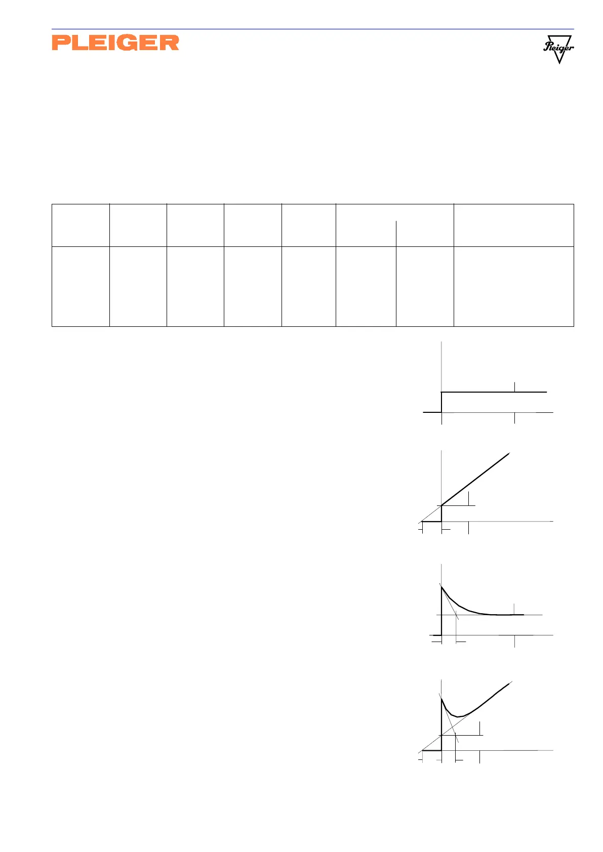
Y
t
Kr
Tn
PI-Structure
Y
t
Kr
Tv/Vd
PD-Structure
Y
t
Kr
Tn
Tv/Vd
PID-Structure
Y
t
Kr
P-Structure
When the cascade step controller “CscStep” is selected, the primary continuous controller always uses
the 1
st
parameter set (
1
) and the secondary 3-Point step controller uses the 2
nd
parameter set (
2
).
5.5.2 Explanatory note on controller structure
The parameterisable structures for the presented controller types are shown in the following table. On
selecting a controller type, the display always shows only the structures which are parameterisable in
accordance with this table!
P controller (proportional-action controller)
In the case of the P controller, a value of the controller output Y is
directly proportionally assigned to each value of the system deviation
xd. The assigned value is set via the gain factor Kr (P gain).
Xp is frequently used instead of Kr. Xp=100 / Kr
PI controller (proportional-plus-integral action controller)
In the case of the PI controller, the value of controller output Y is set
proportional to the system deviation xd (P component), and the
I component, which corresponds to the time integral of the system
deviation, is added to this value. The I component is set via reset time
Tn, which corresponds to the time in which the I component effects a
change in the controller output of a magnitude corresponding to the
P component.
PD controller (proportional-plus-differential action controller)
In the case of the PD controller, a D-component corresponding to the
time differential of the system deviation is added to the controller
output component (P component) which is proportional to system
deviation xd. The D component is set via derivative action time Tv,
which specifies how much earlier the step response of a PD controller
corresponds to a value which is attained by a P controller. A low pass
with the time constant T=Tv / Vd is employed to limit the bandwidth of
the differential element.
PD2 controller (proportional-plus-differential action controller)
This functions in the same manner as the PD controller, whereby the
D2 component corresponds not to the time differential of system
deviation xd but to the time differential of controlled variable X.
PID controller (PI controller with added D component)
PID2 controller (PI controller with added D2 component)
Regarding the D component, see also:
Special function -
Trend compensation (Appendix C1).