Pleiger Elektronik
GmbH & Co. KG
Page: 28 Manual for 362MC Edition: 6/2007 Subject to modifications
1234567890123456789012345678901
1
23456789012345678901234567890
23456789012345678901234567890
23456789012345678901234567890
23456789012345678901234567890
23456789012345678901234567890
23456789012345678901234567890
23456789012345678901234567890
23456789012345678901234567890
23456789012345678901234567890
23456789012345678901234567890
23456789012345678901234567890
23456789012345678901234567890
23456789012345678901234567890
23456789012345678901234567890
23456789012345678901234567890
23456789012345678901234567890
23456789012345678901234567890
23456789012345678901234567890
23456789012345678901234567890
23456789012345678901234567890
23456789012345678901234567890
23456789012345678901234567890
23456789012345678901234567890
23456789012345678901234567890
23456789012345678901234567890
23456789012345678901234567890
23456789012345678901234567890
23456789012345678901234567890
23456789012345678901234567890
23456789012345678901234567890
23456789012345678901234567890
23456789012345678901234567890
23456789012345678901234567890
23456789012345678901234567890
23456789012345678901234567890
23456789012345678901234567890
1
1234567890123456789012345678901
15
15
123456789012345
123456789012345
123456789012345
123456789012345
123456789012345
123456789012345
123456789012345
123456789012345
123456789012345
1234567890
1234567890
1234567890
1234567890
1234567890
1234567890
1234567890
1234567890
1234567890
1234567890
1234567890
1234567890
1234567890
1234567890
1234567890
123456789012345678901234567890121
1
2345678901234567890123456789012
2345678901234567890123456789012
2345678901234567890123456789012
2345678901234567890123456789012
2345678901234567890123456789012
2345678901234567890123456789012
2345678901234567890123456789012
2345678901234567890123456789012
2345678901234567890123456789012
2345678901234567890123456789012
2345678901234567890123456789012
2345678901234567890123456789012
2345678901234567890123456789012
2345678901234567890123456789012
2345678901234567890123456789012
2345678901234567890123456789012
2345678901234567890123456789012
2345678901234567890123456789012
2345678901234567890123456789012
2345678901234567890123456789012
2345678901234567890123456789012
2345678901234567890123456789012
2345678901234567890123456789012
2345678901234567890123456789012
2345678901234567890123456789012
2345678901234567890123456789012
2345678901234567890123456789012
2345678901234567890123456789012
2345678901234567890123456789012
2345678901234567890123456789012
2345678901234567890123456789012
2345678901234567890123456789012
2345678901234567890123456789012
2345678901234567890123456789012
2345678901234567890123456789012
2345678901234567890123456789012
2345678901234567890123456789012
2345678901234567890123456789012
2345678901234567890123456789012
2345678901234567890123456789012
2345678901234567890123456789012
2345678901234567890123456789012
2345678901234567890123456789012
2345678901234567890123456789012
2345678901234567890123456789012
2345678901234567890123456789012
2345678901234567890123456789012
2345678901234567890123456789012
2345678901234567890123456789012
2345678901234567890123456789012
2345678901234567890123456789012
2345678901234567890123456789012
1
123456789012345678901234567890121
65,5
+0,5
137
+0,5
144
72
123456789012345678901234567890121
1
2345678901234567890123456789012
1
123456789012345678901234567890121
140
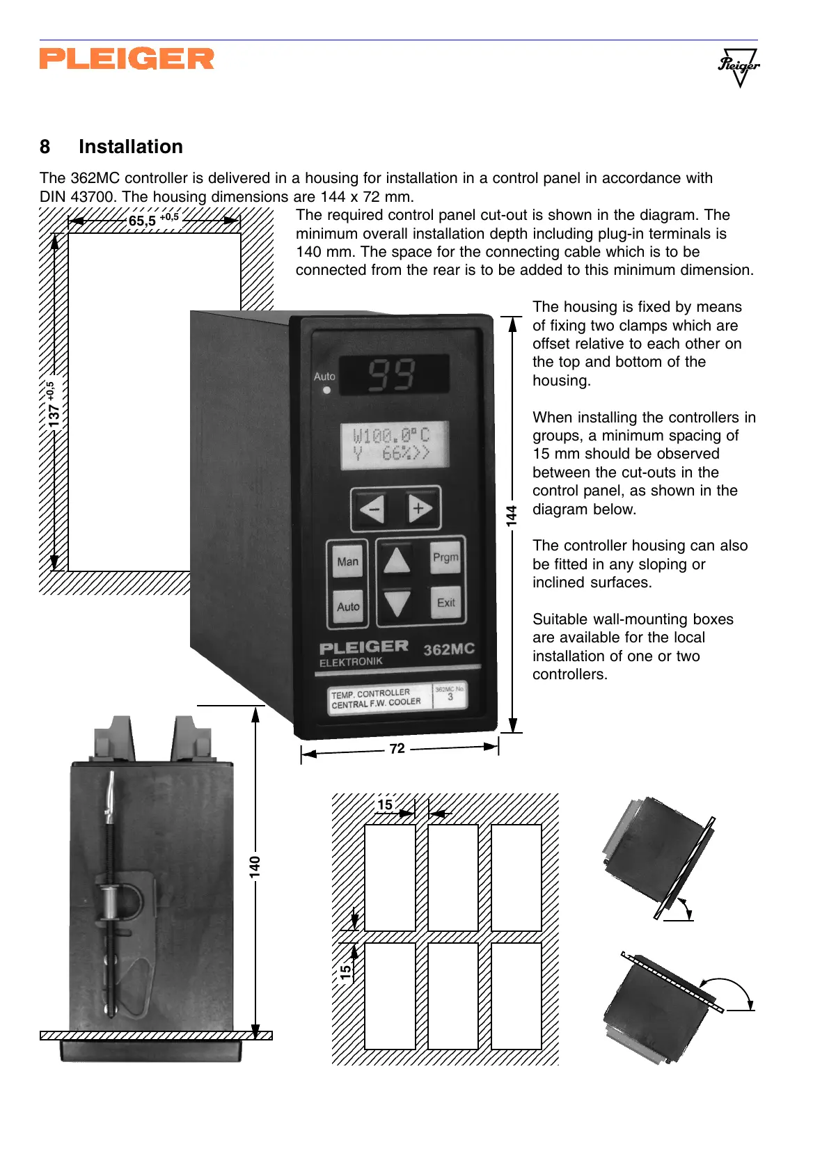
8 Installation
The 362MC controller is delivered in a housing for installation in a control panel in accordance with
DIN 43700. The housing dimensions are 144 x 72 mm.
The required control panel cut-out is shown in the diagram. The
minimum overall installation depth including plug-in terminals is
140 mm. The space for the connecting cable which is to be
connected from the rear is to be added to this minimum dimension.
The housing is fixed by means
of fixing two clamps which are
offset relative to each other on
the top and bottom of the
housing.
When installing the controllers in
groups, a minimum spacing of
15 mm should be observed
between the cut-outs in the
control panel, as shown in the
diagram below.
The controller housing can also
be fitted in any sloping or
inclined surfaces.
Suitable wall-mounting boxes
are available for the local
installation of one or two
controllers.